IM-738 Page 73
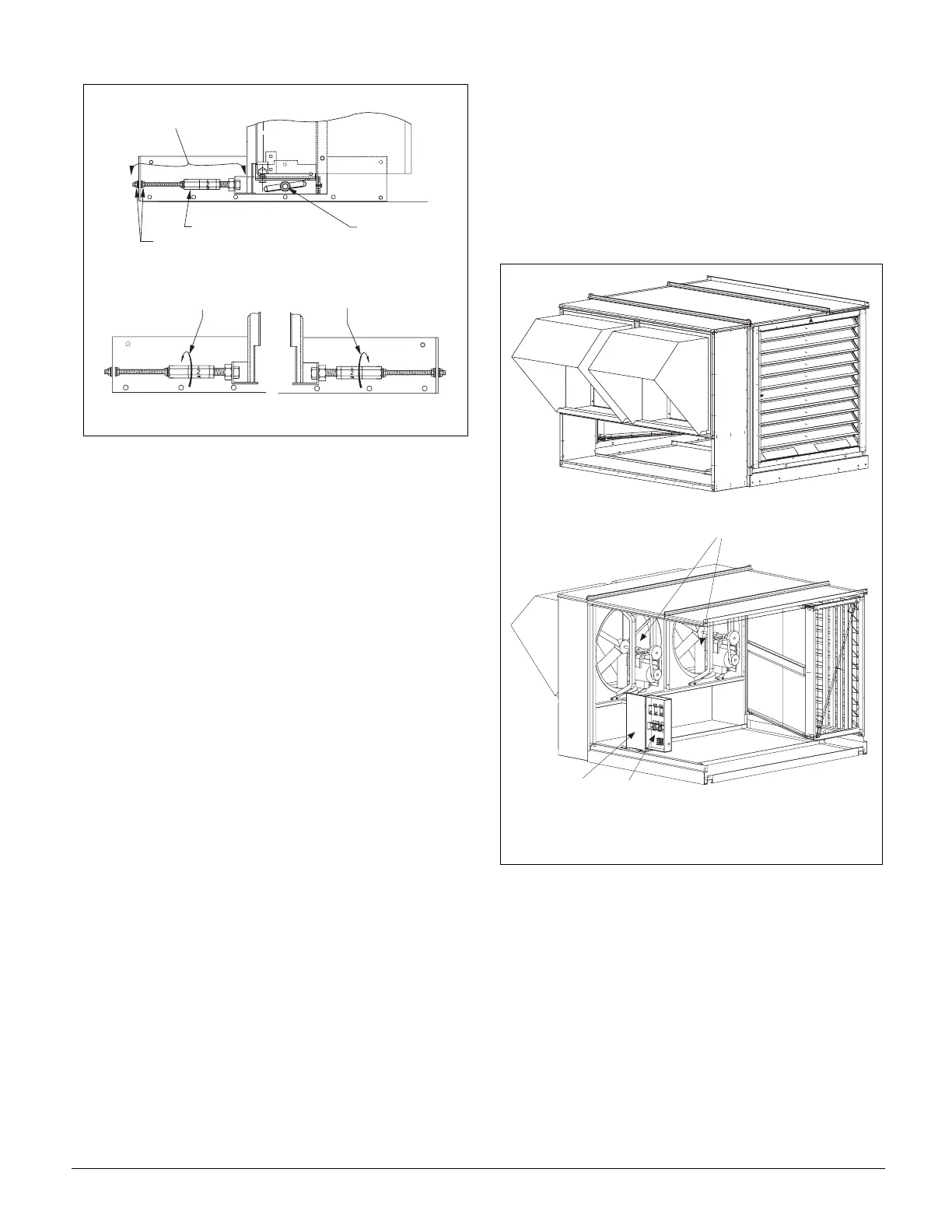
Figure 79. Leveling Adjustment
10. If the value indicated by the LH Lvl Pos=(or RH Lvl
Pos=) parameter is not within the range of 23.64 to
24.08%, a leveling adjustment is required (See Figure 79).
Leveling adjustments are accomplished by shifting the
bottom of the measuring station to the right or left. If the
LH Lvl Pos=(or RH Lvl Pos=) parameter indication is
higher than specified, the bottom of the DesignFlow
frame must be moved closer to the outdoor air damper. If
the LH Lvl Pos=(or RH Lvl Pos=) parameter indication is
lower than specified, the bottom of the DesignFlow frame
must be moved farther from the outdoor air damper.
To make an adjustment, loosen the .25-20 NC lock nut at
the slotted hole at the bottom of the frame. The threaded
adjuster facilitates small accurate movements. Reposition
the two .25-20 NC jam nuts on the threaded rod to make
large adjustments, then use the long adjuster nut to make
fine adjustments. Rotate the long adjuster nut to move the
bottom of the station. Unscrewing the long adjuster nut
from the large bolt makes the assembly longer and
reduces the LH Lvl Pos=(or RH Lvl Pos=) parameter
indication. Screwing in the long adjuster nut from the
large bolt makes the assembly shorter and increases the
LH Lvl Pos=(or RH Lvl Pos=) parameter indication.
After an adjustment is made, retighten the lock nut, gently
rap the base frame to slightly vibrate the assembly and
encourage the vane to seek its equilibrium point. Confirm
that the contact point on the fulcrum is on the vertical
mark on the damper. If the contact point is not on the ver-
tical mark, reposition the fulcrum contact point to line up
with vertical mark (Figure 78 on page 72) and take
another reading.
Important: After an adjustment is made, wait until the
LH Lvl Pos=(or RH Lvl Pos=) value on the keypad/dis-
play stabilizes before making further adjustments. This
can take several seconds.
11. After leveling, remove fulcrum and replace the access
opening covers.
Propeller Exhaust Fan Option
Economizer units may include propeller exhaust or centrifu-
gal return fan options. This section covers maintenance and
operating instructions for the propeller exhaust option. Cen-
trifugal return fan construction, maintenance and operation is
similar to that for supply fans and covered in other sections
of this manual.
Figure 80. 2 Fans with Back Return Shown
Prestarting Checks
Check all fasteners and set screws for tightness. This is espe-
cially important for bearing set screws.
The propeller should rotate freely and not rub on the fan
panel venturi. Rotation direction of the propeller should be
checked by momentarily turning the unit on. Rotation should
be in the same direction as the rotation decal affixed to the
unit or as shown in Figure 81 on page 74. For 3-phase instal-
lations, fan rotation can be reversed by simply interchanging
any two of the three electrical leads. For single phase instal-
lations follow the wiring diagram located on the motor.
The adjustable motor pulley is preset at the factory for the
specified fan RPM. Fan speed can be increased by closing or
decreased by opening the adjustable pulley. Two or three
R I G H T H A N D A D J U S T E R
L E F T H A N D A D J U S T E R
T h r e a d e d A d j u s t e r
A s s e m b l y
J a m N u t s
L o n g A d j u s t e r N u t
L o c k n u t
T o I n c r e a s e L e v e l
P o s i t i o n R e a d i n g
T o R e d u c e L e v e l
P o s i t i o n R e a d i n g
F a n a n d M o t o r A s s e m b l i e s
V F D
S t a r t e r s