Page 44 IM-738
Electrical Installation
Field Power Wiring
Wiring must comply with all applicable codes and ordinances.
The warranty is voided if wiring is not in accordance with
these specifications. An open fuse indicates a short, ground, or
overload. Before replacing a fuse or restarting a compressor or
fan motor, the trouble must be found and corrected.
According to the National Electrical Code, a disconnecting
means shall be located within sight of and readily accessible
from the air conditioning equipment. The unit may be ordered
with an optional factory mounted disconnect switch. This
switch is not fused. Power leads must be over-current pro-
tected at the point of distribution. The maximum allowable
overcurrent protection is shown on the unit nameplate.
All Units
All units are provided with internal power wiring for single or
dual point power connection. The power block or an optional
disconnect switch is located within the main control panel.
Field power leads are brought into the unit through 3" knock-
outs in the bottom of the main control panel. Refer to the unit
nameplate to determine the number of power connections.
Refer to Figure 52.
Note: Refer to certified drawings for dimensions to wire
entry points.
Figure 52. RPS/RDT and RFS Power Wiring Connections
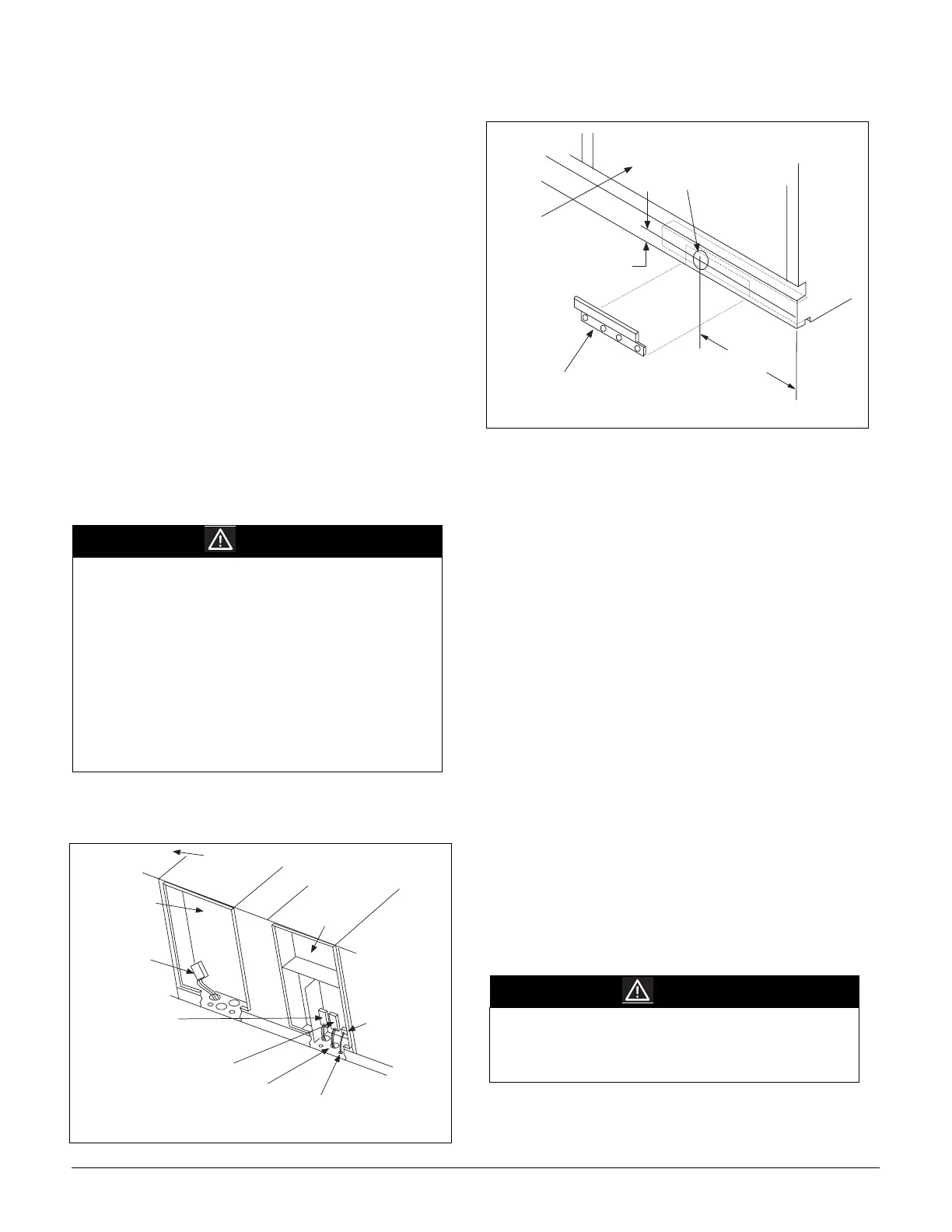
Figure 53. Optional Side Power Wiring Entrance
The preferred entrance for power cables is through the bottom
knockouts provided on the unit. If side entrance is the only
option, a drilling location is provided. The drilling dimensions
must be followed exactly to prevent damage to the control
panel. The dimensions provided are the only possible point of
side entrance for the power cables.
RCS Units
Field power wiring is connected from the main control panel in
the RFS unit to fuse blocks located in the condenser control
panel of the RCS unit. Power leads enter the left front corner of
the condenser control panel through the conduit hubs shipped
with the unit. Refer to Figure 54 and Figure 55 on page 46.
All Units
The minimum circuit ampacity (wire sizing amps) is shown on
the unit nameplate. Refer to Table 17 on page 46 for the rec-
ommended number of power wires.
Copper wire is required for all conductors. Size wires in accor-
dance with the ampacity tables in Article 310 of the National
Electrical Code. If long wires are required, it may be necessary
to increase the wire size to prevent excessive voltage drop.
Wires should be sized for a maximum of 3% voltage drop.
Supply voltage must not vary by more than 10% of nameplate.
Phase voltage imbalance must not exceed 2%. (Calculate the
average voltage of the three legs. The leg with voltage deviat-
ing the farthest from the average value must not be more than
2% away.) Contact the local power company for correction of
improper voltage or phase imbalance.
A ground lug is provided in the control panel for each power
conduit. Size grounding conductor in accordance with Table
250-95 of the National Electrical Code.
WARNING
Hazardous voltage.
May cause severe injury or death.
Disconnect electric power before servicing equipment.
More than one disconnect may be required to de-
energize the unit.
If the unit has a factory mounted disconnect switch, the
switch must generally be turned off to open the main
control panel door. However, the door can be opened
without disconnecting power by turning the screw at the
bottom of disconnect switch clockwise while pulling the
door open. If this is done, however, caution must be
used since power is not removed from the unit or the
controller.
E l e c t r i c H e a t
C o n t r o l P a n e l
D i s c o n n e c t
S w i t c h D S 3
( O p t i o n a l )
P o w e r B l o c k P B 1
o r D i s c o n n e c t
S w i t c h D S 1
D i s c o n n e c t S w i t c h D S 2
( O p t i o n a l )
3 " K n o c k o u t s f o r
P o w e r W i r e ( Q t y . 3
i n M a i n C o n t r o l P a n e l ;
Q t y . 3 i n E l e c t r i c a l
H e a t C o n t r o l P a n e l )
7 / 8 " K n o c k o u t s f o r
1 1 5 V R e c e p t a c l e ( Q t y . 2 )
T e r m i n a l B l o c k
T B 1 f o r 1 1 5 V
S e r v i c e
R e c e p t a c l e
C i r c u i t
M a i n
C o n t r o l
P a n e l
F a n
S e c t i o n
WARNING
Provide proper line voltage and phase balance.
Improper line voltage or excessive phase
imbalance constitutes product abuse. May cause
severe damage to the unit's electrical components.
R e m o v e L i f t i n g B r a c k e t
( I f L o c a t e d H e r e )
B e f o r e D r i l l i n
H o l e
M a i n
C o n t r o l
P a n e l
2 . 7 5 "
( 7 0 m m )
3 " ( 7 6 m m )
M a x D i a .
1 6 "
( 4 0 6 m m )