IM-738 Page 33
RPS/RDT Factory Split at Fan
Field reassembly of an RPS/RDT unit that has shipped split at
the fan takes place in two phases:
Phase 1. Setting the sections and mechanically recoupling
the cabinet.
Phase 2. Reconnecting power and control wiring.
Phase 1. Setting the Sections and Cabinet
Reassembly
The steps required to set the unit and reassemble the cabinet
are shown in Figures . The following items should be noted:
1. Top cap and plywood covers must be removed before the
sections are set together, but the steel retainer clips must
be left in place to secure the bulkhead. Refer to Step 1 and
Figure 39.
2. Both sections must be carefully lowered into place to
make sure that the roof curb engages the recesses in the
unit base.
3. All seams at the split must be caulked watertight after
recoupling the sections, as shown in Step 3 and Figure 40
on page 34.
Phase 2. Reconnecting Power and Control Wiring
The DX coil/condenser section contains power and control
harnesses which have their excess length in the blank or heat
section that is normally immediately downstream of the fan.
Once the sections are physically reconnected, the ends of the
power harness are fed back through the unit base into the junc-
tion box, per the unit’s electrical schematics.
When reconnection of the power wires is complete, the inner
raceway cover in the blank or heat section must be reinstalled.
Figure 41 on page 34 shows a typical installation of the race-
way cover.
Control harnesses can be run by removing the external race-
way covers on either side of the unit split. The excess harness
length can be removed from the external raceway on the DX
side of the split, routed along the raceway through the bushed
hole in the fan section and into the junction box where control
wiring terminal blocks are provided for reconnection. All elec-
trical connections should be made per the unit's electrical sche-
matics. Reinstall the external raceway covers after routing of
the control wires is complete.
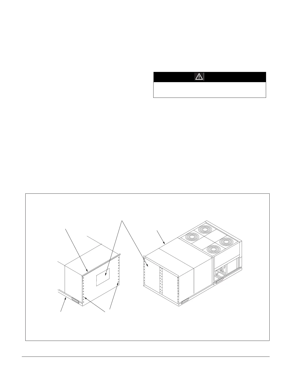
Step 1. Prepare the units for reassembly as shown in Figure 39.
Figure 39. RPS/RDT Split at Fan Reassembly - Step 1
CAUTION
Connect the power block correctly and maintain proper
phasing. Improper installation can cause severe
equipment damage.
R e m o v e t o p c a p a n d
s a v e f o r s t e p 3
R e m o v e p l y w o o d a n d r e t a i n i n g
a n g l e s f r o m u n i t a n d d i s c a r d
D i s c h a r g e e n d o f U n i t
F a n e n d o f U n i t
R e m o v e s c r e w s o n f a n p a n e l , b u t
l e a v e r e t a i n e r c l i p s i n p l a c e ;
s a v e s c r e w s f o r S t e p 3 .