IM-738 Page 95
b. Bad V-belts; lumpy, or mismatched; belt tension too
tight or too loose.
4. Bad bearings, loose bearing hold-down bolts.
5. Motor imbalance.
6. Fan section not supported evenly on foundation.
Periodic Service and Maintenance
1. Check all moving parts for wear every six months.
2. Check bearing collar, sheave, and wheel hub setscrews,
sheave capscrews, and bearing hold-down bolts for tight-
ness every six months.
Setscrews
Setscrews lock bearings, sheaves, locking collars, and fan
wheels to their shafts. It is very important that all setscrews be
checked periodically to provide that they have not loosened. If
this is not done, severe equipment damage could occur.
Using Table 25, check the tightness of all setscrews with a
torque wrench. Note that if the return fan bearings setscrews
must be retightened, a special procedure is required to equally
load both bearings (see “Return Fan Bearing Setscrews” ).
Table 25: Setscrew Minimum Torque Specifications
Return Fan Bearing Setscrews
Because the return fan Is mounted on a vertical shaft, the fol-
lowing procedure must be used to retighten any return fan
bearing setscrews that have loosened. This procedure will pro-
vide that both bearings are equally loaded. If one bearing is
carrying the entire weight of the fan, it could fail prematurely.
1. Loosen the fan belts.
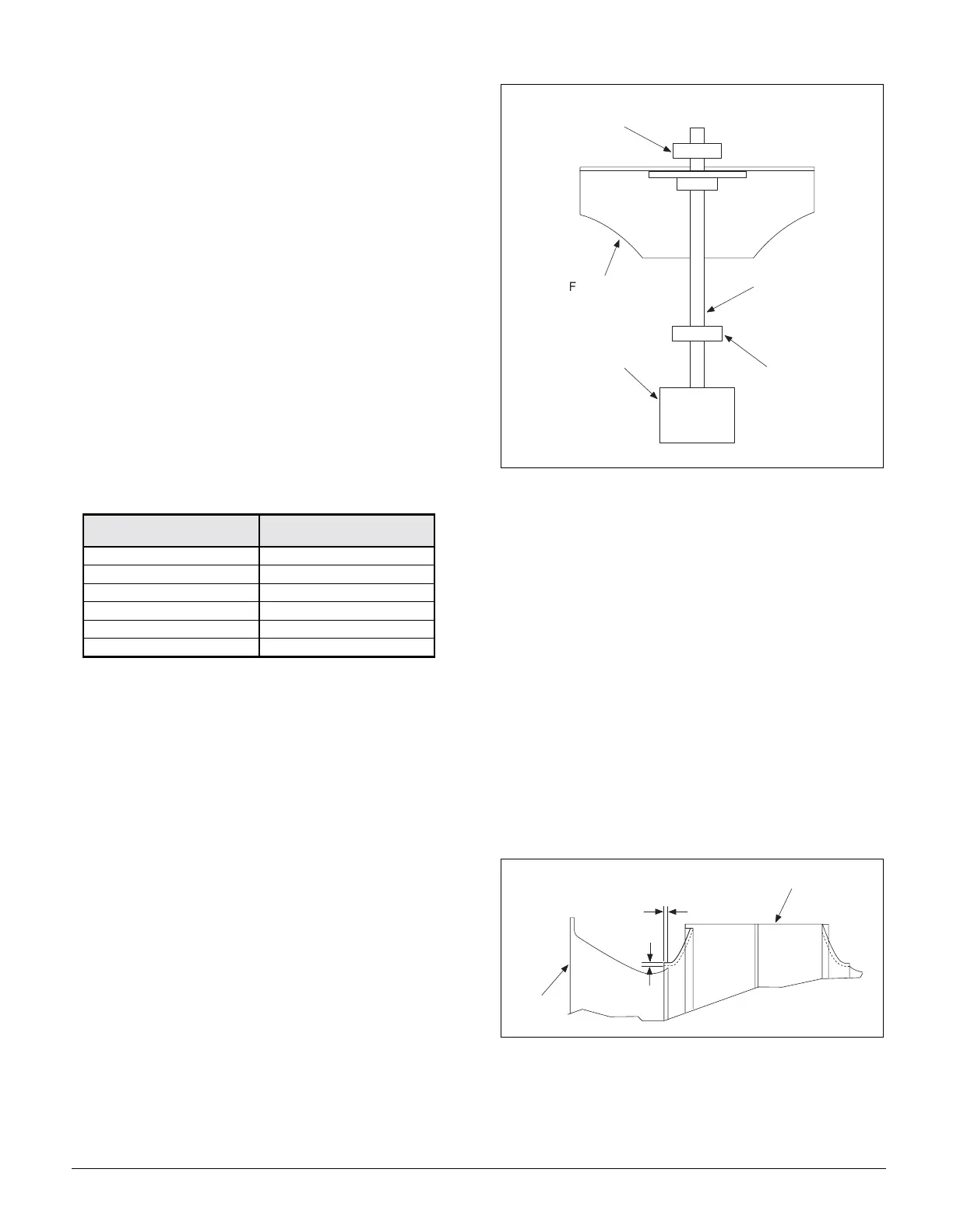
2. Support the weight of the fan and the fan shaft with tim-
bers or some other suitable means (see Figure 95).
Important:In order to maintain proper drive alignment
and fan-to-tunnel clearance, the fan and shaft must not
drop at all when the setscrews are loosened in Step 4.
3. Verify that the upper shaft collar is securely fastened to
the shaft. Check the setscrew torque.
4. Loosen the upper and lower bearing setscrews. The entire
weight of the fan and shaft is now supported by the fan
shaft support.
5. Retighten all bearings to the torque specification given in
Table 25.
6. Remove the fan shaft support and retension the belts.
Figure 95. Return Fan Assembly
Supply Fan Wheel-to-Funnel Alignment
If the unit is equipped with an airfoil or backward curved sup-
ply fan, the fan wheel-to-funnel alignment must be as shown in
Figure 96, Figure 97, Figure 99 & Figure 100 to obtain proper
air delivery and operating clearance. If necessary, adjustments
are made as follows:
1. Verify that the fan shaft has not moved in its bearings.
2. Loosen the fan hub setscrews and move the wheel(s) along
the shaft as necessary to obtain the correct dimension
shown in Table 26, Table 27 & Table 28 on page 96.
3. Retighten the setscrews to the torque specification given in
Table 25 on page 95. Tighten the setscrews over the key-
way first; tighten those at 90 degrees to the keyway last.
4. Verify that the radial clearance around the fan is uniform.
Radial clearance can be adjusted by slightly loosening the
funnel hold-down fasteners, shifting the funnel as
required, and retightening the fasteners.
Figure 96. 20" Airfoil Wheel-to-Funnel (015C-030C)
SETSCREW DIAMETER
(IN.)
MINIMUM TORQUE
(FT.LB)
1/4 5.5
5/16 10.5
3/8 19.0
7/16 29.0
1/2 42.0
5/8 92.0
U p p e r B e a r i n g
a n W h e e l
F a n S h a f t
S u p p o r t
L o w e r
B e a r i n g
F a n S h a f t
F u n n e l
. 2 5 "
. 2 5 "
W h e e l