Page 62 IM-738
Unit Options
Enthalpy Control
Outside Air Enthalpy Control (OAE)
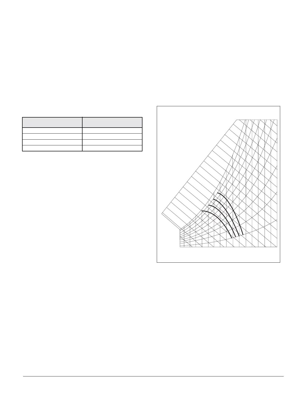
Units with MicroTech II control and an economizer come
standard with an electromechanical enthalpy control device
(OAE) which senses both the humidity and temperature of
the outside air entering the unit. This device has an enthalpy
scale marked A through D. Table 18 shows the control points
at 50% RH for settings A through D. Figure 65 shows this
scale on a psychrometric chart. When the outside air condi-
tions exceed the setting of the device, the outside air dampers
are positioned to the minimum outside air intake position by
the MicroTech II controller.
Table 18: Enthalpy control settings
Differential Enthalpy Control (OAE/RAE)
An optional electric differential enthalpy control arrangement
(OAE/RAE) is available on units with MicroTech II control.
In this configuration a solid-state humidity and temperature
sensing device is located in both the return (RAE) and out-
side intake (OAE) airstreams. This OAE device has the same
A through D scale as the device described above. However,
with the OAE/RAE arrangement the switch on OAE must be
set all the way past the "D" setting. With this done, the
MicroTech II controller will adjust the return and outside air
dampers to use the airstream with the lowest enthalpy.
Low Ambient Start
At low outdoor air temperature conditions, the low ambient
start option provides that the compressors will start and oper-
ate long enough to develop sufficient suction pressure to close
the low pressure switches (LPI and LP2). The low ambient
start sequence of operation is described below. Refer to “Typi-
cal Condensing Unit Control with Control Schematic for RPS
(Controls by Others, 6 Compressor Unit Shown, RCS Has
Minor Variations)” on page 59.
Assume that switches CS I and PS I are closed (lines 807 and
842). When time delay relay TDl times out, relays R5 and R9
(lines 807 and 811) are energized. If cooling is required, the
MicroTech II controller will energize output relay OBAl (line
842), thus energizing liquid line solenoid valve SVl (line 841 ).
At the same time, relay Rll is energized through time delay
relay TDl1 (line 842). The Rll contacts in line 815 then close,
bypassing LP 1. The TD 11 contacts remain closed for 2.75
minutes, and thus Rll remains energized and its contacts
remain closed. When the TD 11 timer expires, it opens the cir-
cuit, de-energizing relay Rll. The Rll contacts then open, and
LPl controls the compressor as usual
Ground Fault Protection
The ground fault protection is designed to protect motors from
destructive arcing ground faults. The system consists of a
ground fault relay and a ground fault current sensor. The
ground fault relay employs solid state circuits that will instan-
taneously trip and open a set of relay contacts in the 115 volt
control circuit to shut the unit down whenever a ground fault
condition exists. The ground fault relay is self powered. The
ground fault sensor is a current transformer type of device
located on the load side of the power block through which the
power wires of all phases are run.
Figure 65. Enthalpy control settings
Phase Voltage Monitor
The phase voltage monitor protects against phase loss (single
phasing) when any one of three line voltages drops to 74% or
less of setting. This device also protects against phase rever-
sal when improper phase sequence is applied to equipment,
and low voltage (brownout) when all three line voltages drop
to 90% or less of setting. An indicator run light is "on" when
all phase voltages are within specified limits. The phase volt-
age monitor is located on the load side of the power block
with a set of contacts wired to the 115 volt control circuit to
shut the unit down whenever the phase voltages are outside
the specified limits.
CONTROL CURVE CONTROL POINT
TEMP. AT 50% RH
A73°F (23°C)
B70°F (21°C)
C67°F (19*C)
D63°F (17°C)
3 5
( 1 . 5 )
4 0
( 4 . 5 )
4 5
( 7 )
5 0
( 1 0 )
6 0
( 1 5 . 5 )
6 5
( 1 8 . 5 )
7 0
( 2 1 )
7 5
( 2 4 )
8 0
( 2 6 . 5 )
8 5
( 2 9 . 5 )
9 0
( 3 2 )
9 5
( 3 5 )
1 0 0
( 3 8 )
1 0 5
( 4 0 . 5 )
5 5
( 1 3 )
1 2
1 4
1 6
1 8
2 0
2 2
2 4
2 6
3 0
3 2
3 4
3 6
3 8
4 0
4 2
4 4
4 6
2 8
E N T H A L P Y B T U P E R P O U N D D R Y A I R
C
B
A
D
D
C
B
A
0 . 5 0
0 . 4 0
0 . 3 0
0 . 2 0
0 . 1 0
0 . 6 0
0 . 7 0
0 . 8 0
0 . 9 0
R E L A T I V E
H U M I D I T Y
3 5
( 1 . 5 )
4 0
( 4 . 5 )
4 5
( 7 )
5 0
( 1 0 )
5 5
( 1 3 )
6 0
( 1 5 . 5 )
6 5
( 1 8 . 5 )
7 0
( 2 1 )
7 5
( 2 4 )
8 0
( 2 6 . 5 )
8 5
( 2 9 . 5 )
9 0
( 3 2 )
9 5
( 3 5 )
1 0 0
( 3 8 )
1 0 5
( 4 0 . 5 )