IM-738 Page 43
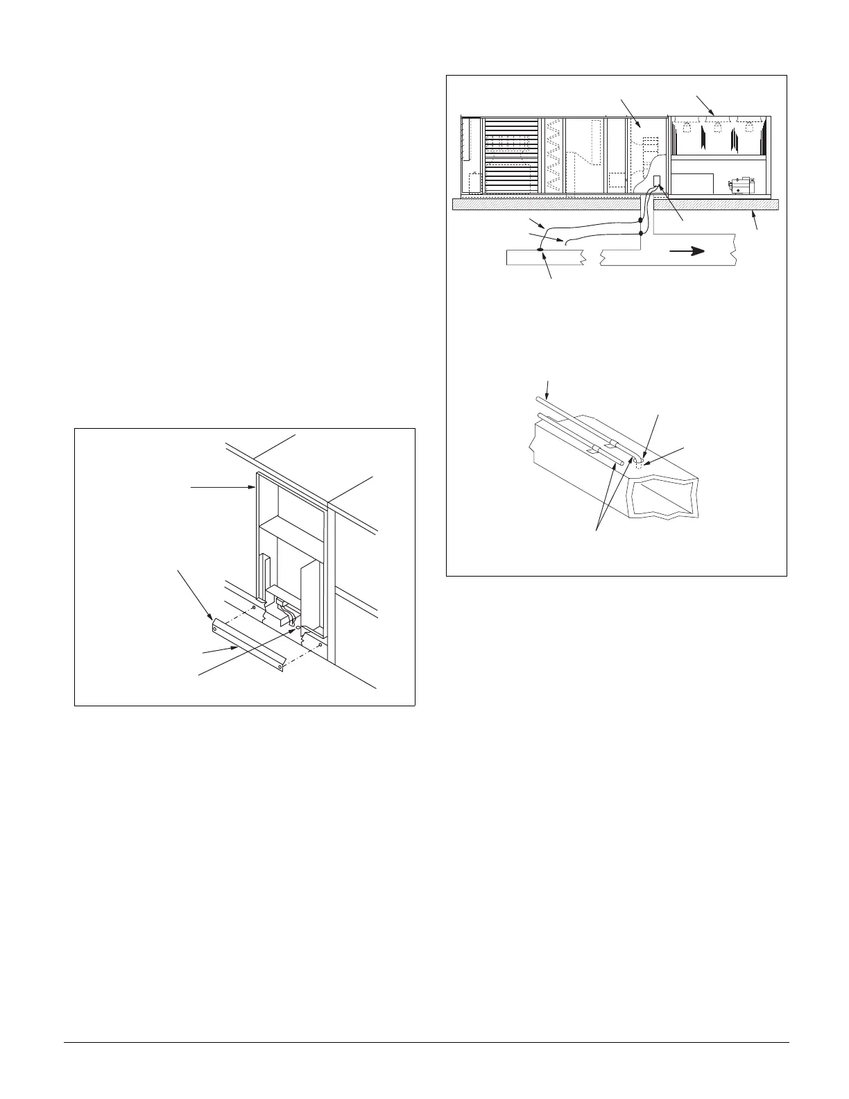
5. Use a static pressure tip (Dwyer A302 or equivalent) or
the bare end of the plastic tubing for the duct tap. (If the
duct is lined inside, use a static pressure tip device.)
6. Install the duct tap so that it senses only static pressure
(not velocity pressure). If an L-shaped pressure tip device
is used, the point must face the airstream. If a bare tube
end is used, it must be smooth, square (not cut at an
angle), and perpendicular to the airstream.
(see Figure 51).
7. Locate the reference pressure (LO) tap somewhere near
the duct pressure tap within the building (see Figure 50 ).
If the reference tap is not connected to the sensor, unsatis-
factory operation will result.
8. Route the tubes between the curb and the supply duct, and
feed them into the unit through the knockout in the bottom
of the control panel (see Figure 50). Connect the tubes to
the appropriate 1/8 inch fittings on the sensors. Make sure
that the sensors do not support the weight of the tubing;
use tube clamps or some other means.
Figure 50. Static Pressure Tubing Entrance Location
Figure 51. Pressure Sensing Tubing Installation
M a i n
C o n t r o l
P a n e l
O u t d o o r S t a t i c
P r e s s u r e T u b i n g
E n t r a n c e ( F i e l d C u t )
I n d o o r S t a t i c
P r e s s u r e T u b i n g E n t r a n c e
C o n t r o l W i r i n g
R a c e w a y C o v e r
M a i n C o n t r o l P a n e l
C o n d e n s e r S e c t i o n
" H I l i n e "
" L O " l i n e
R e m o t e S e n s e P o i n t
S P S 1
R o o f
T u b i n g E x t e n d s
t h r u A p p r o x . 1 / 8 "
R u b b e r
G r o m m e t
D u c t w o r k
( R e m o t e L o c a t i o n )
T o S e n s o r
" H I " i n p u t
T o S e n s o r
" L O " I n p u t
P r e s s u r e S e n s i n g
T u b i n g