IM-738 Page 79
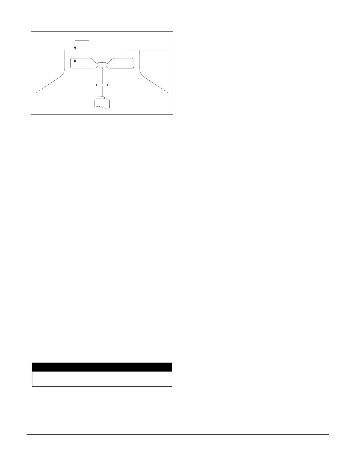
Figure 85. Condenser Fan Blade Positioning
Perform the following procedure:
1. At the keypad, set the cooling setpoints low enough so
that the controller will call for multiple stages of mechani-
cal cooling. On CAV-ZTC units, adjust the "Cooling
Spt=" entry on menu item 12C. On VAV or CAV-DTC
units, adjust the "Cooling Spt=" entry on menu item 12B
and the "Setpoint=" entry on menu item 13A.
2. Place the unit into the "0cc-Cool Only" mode through
keypad menu 11 ("Control Mode").
3. Verify that the low ambient compressor lockout tempera-
ture, "Min OAT=" (menu item 13B), is set below the out-
door air temperature.
Note: Do not attempt to operate the compressors if the
outdoor air is too cool. See the warning statement under
“Compressor Start-up” on page 78.
4. Turn pumpdown switch PS3 to "on."
5. Turn compressor control circuit switch CS1 and pump-
down switch PS1 to "on."
Now refrigeration circuit #1 is enabled and circuit #2 is
disabled. After CS1 is closed, time delay relay TD1 starts
its 5-minute timing cycle. Note that if the unit has an
economizer and the outdoor air enthalpy is low, the econo-
mizer must fully open before the controller will energize
mechanical cooling. When the outdoor air damper has
fully opened and the TD1 timer has expired, liquid line
solenoid valve SV1 should open. If the solenoid valve
does not open, do the following:
a. Verify that there is a call for cooling by checking the
display on menu 1, "Unit Status."
b. Verify that the oil safety control is not tripped. If it is, it
must be manually reset.
c. Trace the circuits.
6. Verify that compressor #1 starts. On units without optional
low ambient start, the compressor should start shortly after
the solenoid valve opens. On units with low ambient start,
the compressor should start when the solenoid valve opens.
If the compressor motor hums but does not run, verify that
it is getting three-phase power.
The compressor should operate continuously while there is
a call for cooling. If the compressor stops because the oil
pressure switch trips, see "Oil Pressure" below. If the
compressor cycles on its low pressure switch, do the fol-
lowing:
a. Verify that the circuit is not short of refrigerant.
b. Check for low airflow.
c. Check for clogged filters.
d. Check for restricted ductwork.
e. Check for very low temperature return air entering
the unit.
f. Verify that the liquid line components, expansion valve,
and distributor tubes are feeding the evaporator coil.
g. Verify that all air handling section panels are closed.
h. Verify that the suction service valve and the liquid line
service valves are completely open.
7. Verify that the compressor stages properly. When com-
pressor #1 starts, the unloaders (if any) should be ener-
gized. As the controller stages and further loads the
compressor, it de-energizes the unloaders. For more infor-
mation on staging sequences, see the "Controller Outputs"
section of Bulletin No. IM 483, "MicroTech II Applied
Rooftop Unit Controller."
8. Verify that the condenser fans are cycling and rotating
properly (blowing air upward). When the compressor
starts, at least one condenser fan should also start. The
FanTrol pressure and temperature switches should cycle
the remaining fans as required to maintain the refrigerant
head pressure. Refer to the unit wiring diagrams and to
“Condenser Fan Arrangement” on page 6.
9. Check the oil level in the compressor sightglass. See "Oil
Pressure" below. If a low oil level and heavy foaming is
observed in the compressor sightglass, it is possible that
excess liquid refrigerant is returning to the compressor.
Check the suction superheat, see “Checking Superheat”
on page 80; it should be between 10°F (-12°C) and 13°F
(-11°C). See “Expansion Valve Superheat Adjustment” .
10.Close solenoid valve SV1 by turning switch PS1 to "Off."
The circuit should pump down and then the compressor(s)
should stop. Place the unit into the "Occ-Fan Only" mode
through keypad menu 11.
11.Check refrigerant circuit #2 by repeating steps 2 through 10,
substituting circuit #2 component nomenclature for circuit
#1 nomenclature (CS2, PS2, TD2, SV2, compressor #2).
Note: The unit is wired for continuous, recycling pump-
down. If switches CS1 and CS2 are closed, the compressor
will start and pump down again whenever the low pressure
switch closes. Small leakages through the compressor
valves and liquid line solenoid valves can cause the circuit
to pump down periodically during the off cycles. This is
usually normal. If a compressor pumps down more than
once every 15 minutes during an off cycle, the unit should
be serviced.
12.Verify the condenser refrigerant subcooling at full capac-
ity is between 12-16°F.
NOTICE
Venting refrigerant to atmosphere is not allowed per
most local laws and/or codes.
2 . 2 5 "