Table of Contents
TOC - 3
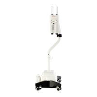
13 - Injector Head
Description of Injector Head 13 - 1
Description of Motor and Drive System 13 - 2
Description of Feedback Pots 13 - 2
Description of Syringe Heat Maintainer 13 - 2
Circuit Descriptions:
Injector Head Card 13 - 2
SIP Switch Settings 13 - 6
Block Diagram: Head Card 13 - 7
14 - Imaging System Interface
Description of Imaging System Interface 14 - 1
Interfacing Cautions 14 - 2
Imaging System Interface Circuits 14 - 4
Block Diagram: Imaging System Interface 14 - 6
Z5 Option 14 - 7
Schematic: Siemens Interface 14 - 8
Schematic: Phillips Interface 14 - 9
15 - Troubleshooting Guide
Required Test Equipment 15 - 1
Service Access Card (SAC) 15 - 2
SAC Test Points 15 - 3
Troubleshooting Guide:
Introduction 15 - 6
General Troubleshooting Guidelines 15 - 7
Suggested Troubleshooting Sequence 15 - 9
Message Faults: 15 - 10
Non-Message Faults: 15 - 32
Dead Unit 15 - 33
No Drive 15 - 34
Will Not Inject 15 - 35
Garbled Message 15 - 35