32 man_digiflex_com_en_02_5.doc
3.8.1.3 Further Fields of Application
(1) T-joints (Tapped joints) occur when a conductor pair leading to an
extension is tapped off a pair in the main line. Halving the
characteristic impedance at the tap or bridge will result in a fault
similar to a short circuit (negative reflection). The trace on display is
difficult to assess if a pair of conductors is tapped at many points
unless precise information about the structure of the cable network is
available.
(2) Some telephone lines are coil-loaded in order to increase the
inductance of the line and thereby improve the transfer characteristic
of a trunk line. The
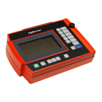
Digiflex Com will interpret the coils used for the
inductive loading of the system as open ends. Connect the instrument
to some point behind the coil if you want to locate a fault which is
situated beyond the bounds of a coil-loaded section.
3.8.2 Testing a Cable with Known Nominal Velocity of Propagation
NVP or with Known Pulse Propagation Velocity (
v
/
2
)
In many instances the route and characteristics of the cable are known in
which case the nature and position of the fault can located quickly. In such
circumstances proceed as follows:
(1) De-energise or disconnect the Faulty pair and, where appropriate, a
good reference, if possible. When a test has to be performed under
voltage, make sure that the voltage does not exceed 250 V AC/DC.
(2) Use the test leads supplied with the
Digiflex Com to connect the Faulty
pair to Line 1 and, when appropriate, the good pair to Line 2.
(3) Press key to switch the
Digiflex Com on. Menu Measurement will
appear after a few seconds.
(4) Press key (Line) to select the appropriate mode of measurement, e.g.
Diff when a good pair is available or L1 when you test the Faulty pair
alone.

 Loading...