man_digiflex_com_en_02_5.doc 21
3. OPERATION
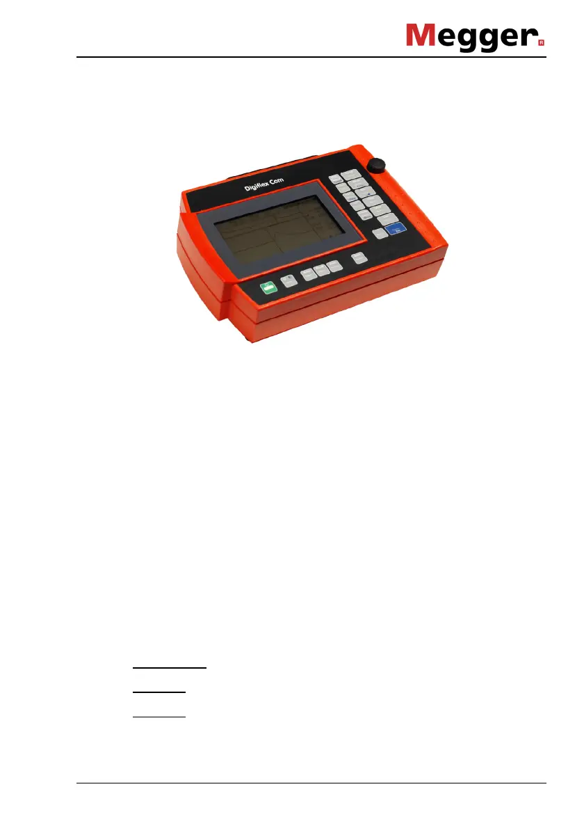
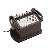
Fig 1
Digiflex Com, Front View
3.1 Measuring Terminals
L1
In general, these measuring sockets are used for connecting the
faulty line or line to be tested. When using this configuration please
make sure that your
Digiflex Com is set to mode L1. In mode NEXT
this pair of sockets is used for receiving the crosstalk.
L2
In general, these measuring sockets are used for connecting a
faultless pair of conductors to be used as a reference for comparison
with the test object connected to L1. In mode Diff this facilitates the
detection of small fault reflections in the tested line connected to L1
because each reflection caused by a junction or terminal occurs in
both lines at the same distance and approximately the same size and
will thus almost be cancelled out in the reflectogram due to the
applied method of subtraction. In mode L1, a line that is possibly
connected to L2 will not have any influence whatsoever on the test.
Mode NEXT
: This pair of sockets will carry the transmitted pulse.
Mode Alt
: Testing is carried out alternately on L1 and L2.
Mode L2
: Reflection measurement of L2