AJ0383DE ZP-AJ01E TRAX
35
5 OPERATING INSTRUCTIONS
3] When reading is stable (manual mode), stop
measurement and the result is displayed.
In autostop, measurement will be automati-
cally stopped.
4] Perform next measurement.
5] Discharge is automatic.
WARNING
Do not remove any cables until discharge
is finalized.
Winding resistance with transformer
configuration
1]
Enter the transformer configuration and
select winding(-s) for test.
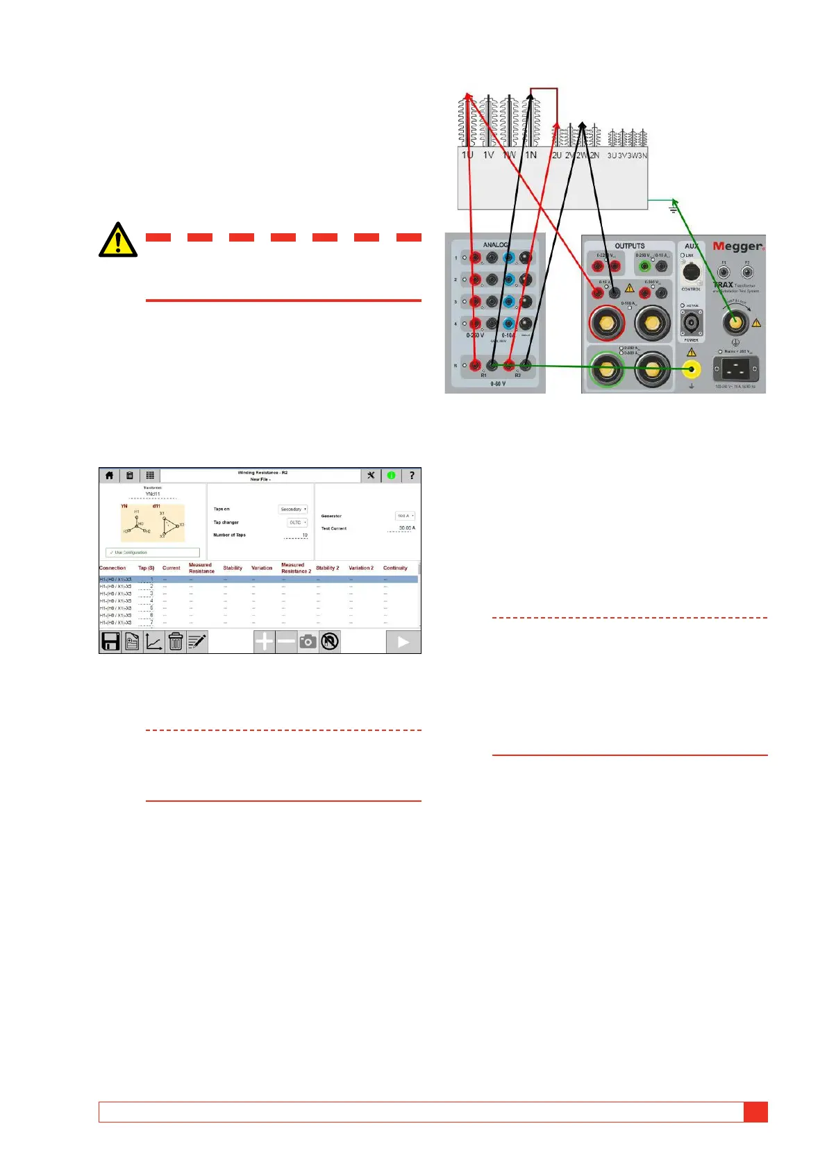
2] Connect the cables as described, e.g. current
H1- X3 with H3X0 short, R1 H1-H3, R2 X0-X3.
3] Connect current and voltage leads to the test
object.
Pressing “?” will show the connection.
Note This is a 4-wire method. Connect voltage
sense leads “inside” the current leads connec-
tors. The connectors must NOT touch each
other.
4] Select test current and start measurement.
If no OLTC and no taps
1] When reading is stable, stop measurement
and the result is displayed.
2] Reconnect cables and perform test on next
phase.
Resistance variation between windings will be dis-
played when all phases are measured.
If taps with DETC (de-energized tap changer)
Note In field tests, the transformer is often tested
with the DETC position “as found” and it may
not be recommended to change the DETC
selector switch. Make sure to confirm with
the transformer owner before making any
changes.
DETC and OLTC measurements should be
performed by winding (see global settings).
1] When reading is stable, stop measurement
and the result is displayed
2] Stop generator.
3] Operate tap changer.
4] Start generating, when reading is stable, stop
measurement and the result is displayed
5] Repeat from step 2 until last tap.
6] Reconnect cables and perform test on next
phase.
Winding variation will be displayed when all phases
are measured.