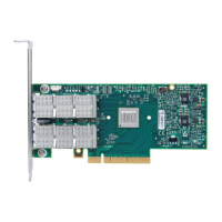
ConnectX®-3 Ethernet Single and Dual QSFP+ Port Adapter Card User Manual Rev 2.0
Mellanox Technologies
19
5. Secure the adapter with the adapter clip or screw.
6. Close the system case.
3.6 Cables and Modules
To obtain the list of supported cables for your adapter, please refer to “Mellanox Products
Approved Cable Lists” at:
www.mellanox.com/related-docs/user_manuals/Mellanox_approved_cables.pdf.
3.6.1 Cable Installation
1. All cables can be inserted or removed with the unit powered on.
2. To insert a cable, press the connector into the
port receptacle until the connector is firmly
seated.
3. After inserting a cable into a port, the Green L
ED indicator will light when the physical con-
nection is established (that is, when t
he unit is powered on and a cable is plugged into the port
with the other end of the connector plugged into a functioning port). See Section 7.3,
“Adapter LED Operation,” on page 48.
4. After plugging in a cable, lock the connector using the latching mechanism part
icular to the
cable vendor. When a logical connection is made the Yellow LED will light. When data is
being transferred the yellow led will blink. See Section 7.3, “Adapter LED Operation,” on
page 48.
5. Care should be taken as not to impede th
e air exhaust flow through the ventilation holes. Use
cable lengths which allow for routing horizontally around to the side of the chassis before
bending upward or downward in the rack.
6. To remove a cable, disengage the locks and sl
owly pull the connector away from the port
receptacle. Both LED indicators will turn off when the cable is unseated.
a.
Do not use excessive force when seating the card, as this may damage the system or
the adapter.
When installing cables make sure that the latches engage.
Always install and remove cables by pushing or pulling the cable and connector in a
straight line with the card.

 Loading...