3.
4.
5.
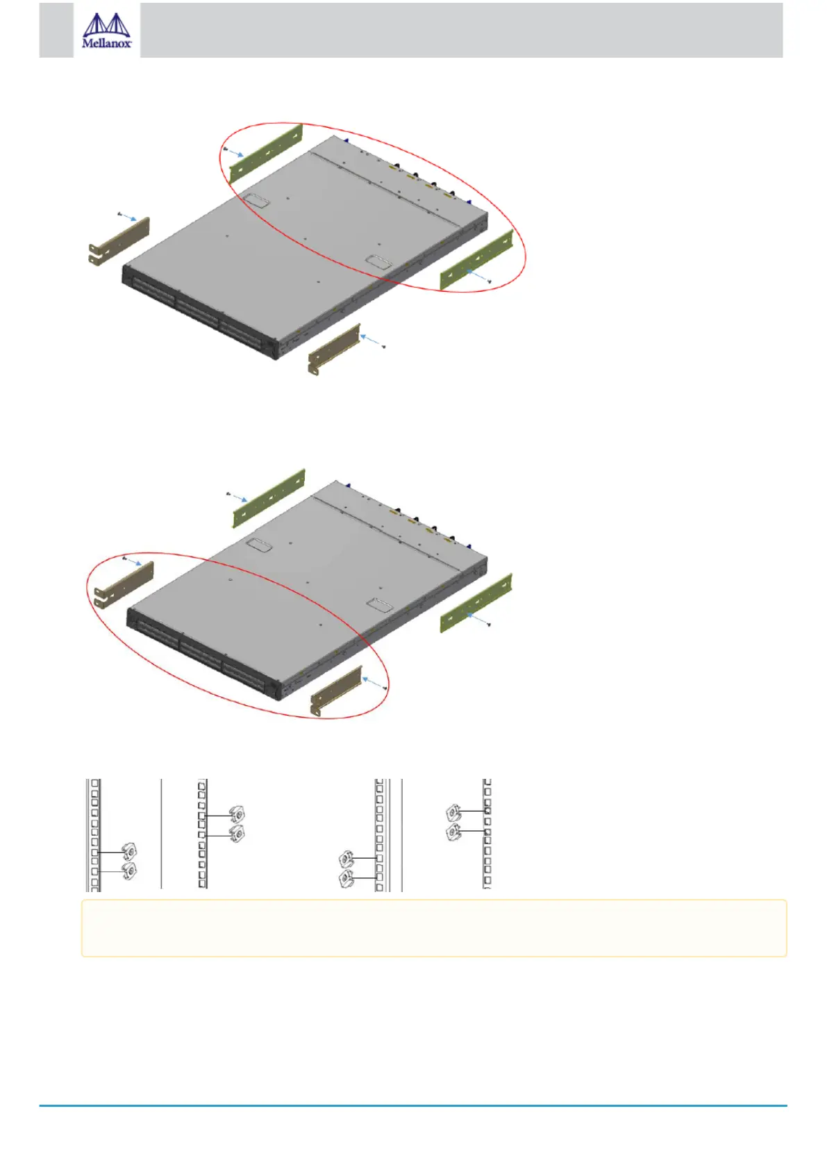
Attaching the Rails to the Chassis
Attach the left and right rack mount brackets (B) to the switch, by gently pushing the switch chassis’ pins through the slider
key holes, until locking occurs. Secure the system in the brackets by screwing the remaining 2 flat head Phillips screws (E) in
the designated points with a torque of 1.5±0.2 Nm.
Attaching the Brackets to the Chassis
Install 8 cage nuts in the desired slots of the rack: 4 cage nuts in the non-extractable side (in the top and bottom holes only)
and 4 cage nuts in the extractable side.
Installing the Cage Nuts
While your installation partner is supporting the system’s weight, perform the following steps:
Mount the system into the rack enclosure, and attach the brackets installed on the system to the rack’s posts. Secure the
brackets to the rack’s posts by inserting four M6 screws in the designated cage nuts, as described in the figure below. Do not
tighten the screws yet.
While each rack U (unit) consists of three holes, the cage nut should be installed vertically with its ears engaging the
top and bottom holes only.
 Loading...