•
•
1.
2.
3.
4.
5.
In case there are cables that cannot bend within the rack, or in case more space is needed for cable bending radius, it is
possible to recess the connector side or the FRU side by 3” or 4” (7.62 or 10.16cm) by optional placement of the system’s
rails.
The FRU side is extractable. Mounting the sliding rail inverted to the system will allow you to slide the FRU side of the
system, in and out.
To mount the system into the rack:
Insert 10 cage nuts into the desired slots of the rack: 4 cage nuts in the non-extractable side and 6 cage nuts in the extractable
side.
Installing the Cage Nuts
Mount both of the outer rails (C+D) into the rack (as illustrated below), and use 8 standard pan-head screws (E) to fix them to
the rack. Do not tighten the screws yet.
Mounting the Outer Rails into the Rack
If cable accommodation is required, route the power cable and/or Eth cable through either of the outer rails.
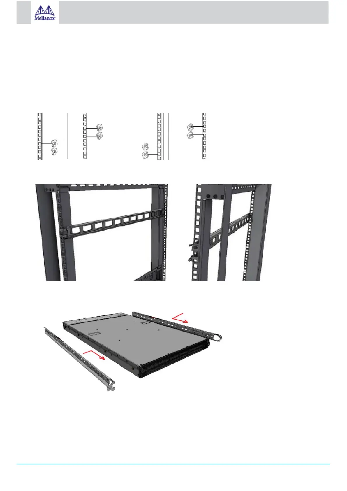
Attach left and right inner rails (A+B) to the switch sides, by gently pushing the switch chassis’ pins through the slider key
holes, until locking occurs.
Attaching the Inner Rails
Secure the chassis in the inner rails by screwing the 2 flat head Phillips screws (F) in the designated points with a torque of
1.5±0.2 Nm.
Securing the Chassis in the Inner Rails
 Loading...