Engineer’s Menu 3 TS790+ & TS900+ Installation Manual
50
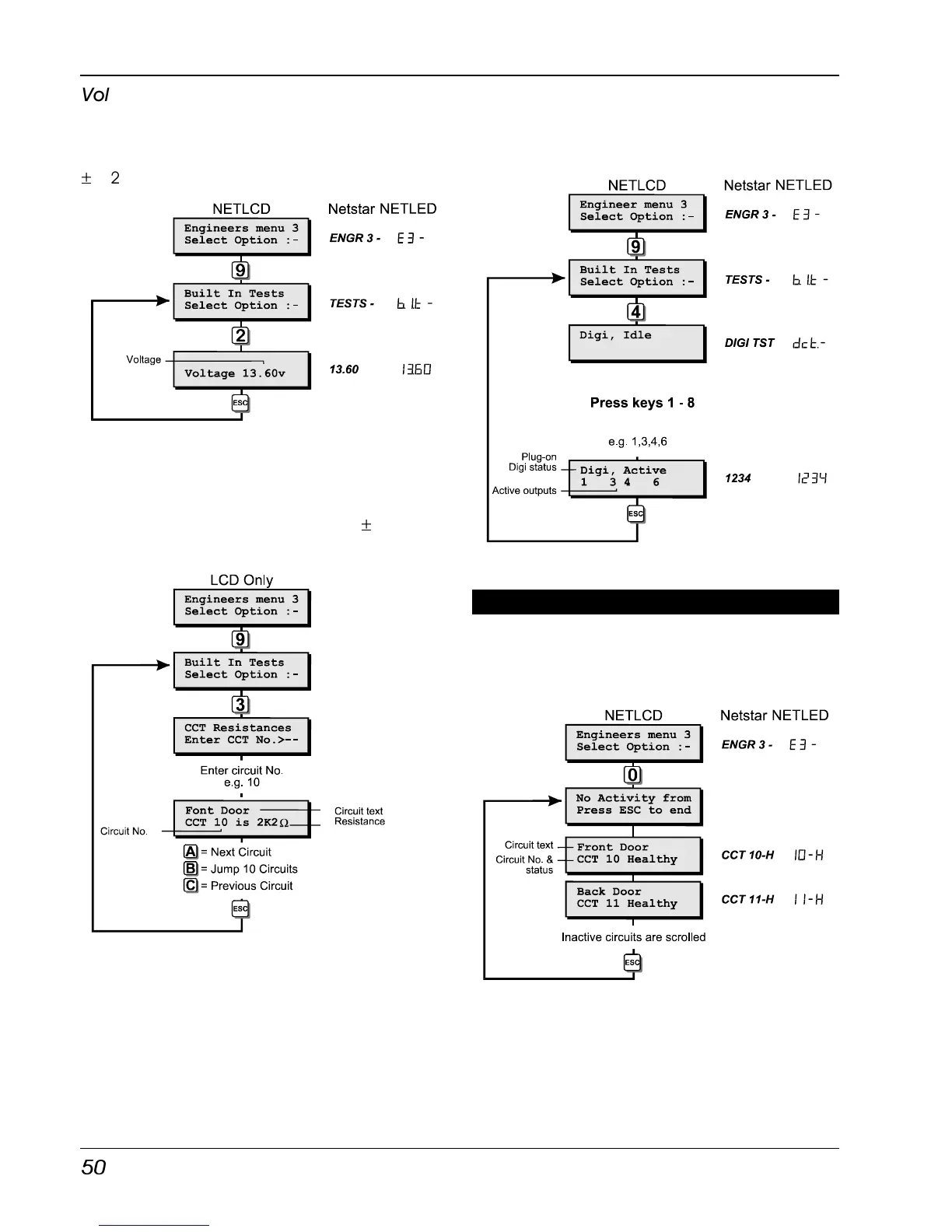
Voltage
When this test option is selected the battery
charging voltage at the control panel is
displayed, the accuracy of this measurement is
±
0.2V.
System Voltage Flowchart
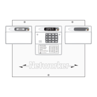
View Circuit Resistance (LCD Only)
When this test routine is selected the resistance
for each detection circuit may be measured,
the accuracy of this measurement is
±
0.1
KOhms.
View Circuit Resistances
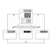
Test Digi Outputs
This test routine allows any outputs or digi
channels that have been programmed as
“FIRE”, “P.A.”, “ALARM” and “SET” to be tested.
If the system is fitted with a plug-on digicom the
top line of the display will show the status of the
communicator.
When you leave this test routine the digi
channels and outputs are returned to their
normal condition.
Test Digi Outputs Flowchart
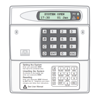
View Inactive Circuits [3.0]
Circuits with the “Flagged” attribute that have
not been activated whilst the system was unset
can be viewed using this menu option, see
"Circuit Attributes" for full details on page 29.
View Inactive Circuits Flowchart