200/225/250/275 VERADO 4-STROKE
Page 32 / 51 90-10238051
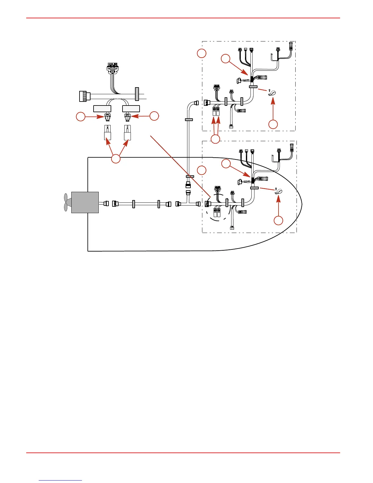
NOTE: For dual helm application - Remove CAN 1 and CAN 2 terminator resistors from
helm 1 (helm closest to the engine), and seal connectors with weather caps.
3677
a
c
c
b
d
d
e
f
g
h
Terminator
CAN 1
Terminator
CAN 2
Dual Helm Application
a - Helm 2 (upper helm)
b - Helm 1 (lower helm)
c - DTS command module harness
d - Clamp or cable tie
e - CAN 1 connector
f - CAN 2 connector
g - Weather caps
h - Terminator resistors, blue (CAN1 &
CAN2)
MODULE INSTALLATION
• Although the Command Module connection is watertight, it is recommended that it be
mounted in an area that stays relatively dry.
• Mount in an area where the wiring connection will not get stepped on or disturbed.
• Mount in an area that is accessible for troubleshooting and servicing the system.
 Loading...