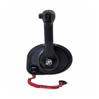
4000 MPC GEN II PISTOL GRIP REMOTE CONTROL INSTALLATION INSTRUCTIONS
Page 16 / 22 90-8M0103111 FEBRUARY 2015
NOTE: The control handle is a painted component. Protect the control handle paint from damage when removing the
throttle only button.
a - Throttle only button
b - Bezel
Wire Color Code Abbreviations
Wire Color Abbreviations
BLK Black
BLU Blue
BRN Brown GRA Gray
GRN Green ORN Orange
PNK Pink PPL Purple
RED Red TAN Tan
WHT White YEL Yellow
LT Light DK Dark
Lanyard Stop Switch Wiring Diagrams
Mercury/Mariner Outboards 40 HP through 225 (3.0 Liter), Force (1993 and Newer)
a - Neutral start safety
leads
b - Bullet or eyelet
connectors
c - Ignition key switch
d - Engine harness
connector
e - Power trim connector
f - Lanyard stop leads
g - 3 pin plastic
connector
a
b
b
c
d
e
f
g
YEL/RED
YEL/RED
YEL/RED YEL/RED
BLK
BLK
BLK/YEL
BLK/YEL
24976

 Loading...