EasyManua.ls Logo

Mercury 4000 MPC GEN II - User Manual

Mercury 4000 MPC GEN II
22 pages
Print Icon
To Next Page IconTo Next Page
Loading...
90-8M0103111 FEBRUARY 2015 © 2015 Mercury Marine Page 1 / 22
4000 MPC GEN II PISTOL GRIP REMOTE
CONTROL INSTALLATION INSTRUCTIONS
IMPORTANT: This document guides our dealers, boatbuilders, and company service personnel in the proper installation or
service of our products. If you have not been trained in the recommended servicing or installation procedures for these or
similar Mercury Marine products, have the work performed by an authorized Mercury Marine dealer technician. Improper
installation or servicing of the Mercury product could result in damage to the product or personal injury to those installing or
operating the product.
NOTE:
After completing installation, place these instructions with the product for the owner's future use.
Pistol Grip Remote Control with Fingertip Neutral Lock Release
24953
Notice to Installer
Throughout this publication, Warnings and Cautions (accompanied by the International Hazard Symbol) are used to alert the
installer to special instructions concerning a particular service or operation that may be hazardous if performed incorrectly or
carelessly. Observe them carefully.
These "Safety Alerts," alone, cannot eliminate the hazards that they signal. Strict compliance to these special instructions
when performing the service, plus common sense operation, are major accident prevention measures.
!
WARNING
Indicates a hazardous situation which, if not avoided, could result in death or serious injury.
!
CAUTION
Indicates a hazardous situation which, if not avoided, could result in minor or moderate injury.
NOTICE
Indicates a situation which, if not avoided, could result in engine or major component failure.
IMPORTANT: Indicates information or instructions that are necessary for a particular step or action.
NOTE: Indicates information that helps in the understanding of a particular step or action.
This instruction sheet has been written and published by the service department of Mercury Marine to aid installers when
installing the products described herein.
Question and Answer IconNeed help?

Do you have a question about the Mercury 4000 MPC GEN II and is the answer not in the manual?

Summary

Notice to Installer

Safety Definitions

Explains WARNING, CAUTION, NOTICE, IMPORTANT, and NOTE terms used in the manual.

GEN II Pistol Grip Remote Control Features and Operation

Control Handle Functions

Details the neutral lock, throttle-only, power trim, and lanyard stop buttons/switches.

GEN II Series Panel Mount Remote Control Installation

Mounting Clearances and Cable Requirements

Specifies minimum cable bend radius and required clearance for panel mount installations.

Bezel Installation and Clearances

Guides the installation of the bezel and ensures proper clearance for components.

Bezel Location and Drilling Procedure

Details how to select the mounting area and drill for the control module.

Selecting and Routing Remote Control Cables

Covers selecting, routing, and lubricating the correct shift and throttle cables.

Throttle and Shift Cable Installation

Control Cable Anchor Attaching Location

Specifies where to attach shift and throttle cables based on outboard models.

Typical Cable Installation and Threadlocker Use

Explains standard installation procedures and the importance of threadlocker for cable screws.

Securing Control Cables and Back Plate

Details tightening cable screws and securing the back plate to the control module.

Pistol Grip Remote Control with Fingertip Lock Release Installation

Module to Bezel Installation and Trim Switch Leads

Guides the installation of the remote control module to the bezel, ensuring trim switch lead freedom.

Wiring Connections and Bushing Installation

Covers connecting trim switch connectors and installing the module assembly bushing.

Control Handle Assembly and Wire Routing Checks

Details securing the control handle and checking trim switch wire routing to prevent failure.

Throttle Button and Safety Switch Connections

Explains throttle only button installation and connecting neutral start safety switch leads.

Throttle Only Button Removal and Cable Clearance

Describes how to remove the throttle only button and notes cable clearance requirements.

Wiring and Diagrams

Wire Color Codes and Lanyard Stop Switch Diagram

Provides wire color abbreviations and the wiring diagram for Mercury/Mariner outboards.

MerCruiser Gasoline Model Wiring Diagram

Shows the wiring diagram for MerCruiser single-engine gasoline models.

MerCruiser Diesel Model Wiring Diagram (D1.7 L-D4.2 L)

Displays the wiring diagram for specific MerCruiser diesel engine models.

MerCruiser Diesel (D7.3 L) Wiring Diagram

Presents the wiring diagram for the MerCruiser D7.3L diesel engine.

Mechanical Remote Control Maintenance

Maintenance Responsibilities and Intervals

Outlines owner responsibilities and recommended maintenance schedules for the remote control.

Fastener Checks, Lubrication, and Cable Inspection

Details checks for fasteners, lubrication points, and cable condition for maintenance.

GEN II Series Panel Mount Remote Control Bezel Template

Template Usage and Mounting Considerations

Explains how to use the template and considerations for mounting the control module.

Template Mounting and Cutout Details

Provides specific instructions for drilling and cutting based on the template.

Overview

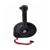
The 4000 MPC GEN II Pistol Grip Remote Control is a panel-mount control unit designed for marine applications, facilitating the operation of Mercury, Mariner, Force, and MerCruiser engines. It integrates throttle, shift, trim, and safety functions into a single, ergonomic pistol grip design.

Function Description

The remote control manages both throttle and shift operations. The control handle moves forward from neutral for forward gear and increased speed, and backward from neutral for reverse gear and increased speed. A key feature is the Neutral Lock Button, which prevents unintentional shifting into gear. To shift, the button must be pressed and held while moving the control handle out of neutral. The Throttle Only Button allows for throttle advancement without engaging the engine's shift mechanism, useful for starting the engine in neutral. This button can only be pressed and held when the control handle is in the neutral position.

For equipped models, a Power Trim Switch allows for trimming or raising the drive unit, beneficial for trailering, launching, beaching, or shallow water operation. A Lanyard Stop Switch is also included (or can be installed as an accessory) to turn off the engine if the operator moves too far from their position, such as in an accidental ejection. The lanyard, typically 122 to 152 cm (4 to 5 feet) when stretched, connects the operator to the switch.

The control handle also features a Control Handle Friction Adjustment Nut, which allows the user to increase or decrease the tension on the control handle. This adjustment helps prevent "creep" of the handle and is factory-set but can be customized.

Important Technical Specifications

  • Minimum Bend Radius for Control Cables: 30.5 cm (12 in.). For applications requiring a smaller radius, or lengths longer than 5.5 m (18 ft), Mercury/Quicksilver GEN II Platinum or Premium cables are required.
  • Mounting Panel Thickness: Maximum 2.54 cm (1 in.).
  • Control Module Mounting: Can be rotated in 30° increments.
  • Control Cable Clearance: A minimum of 45.7 cm (18 in.) straight routing clearance is required for control cables exiting the remote control module. No anchors, clamps, cable ties, or other items should be secured within this clearance space.
  • Torque Specifications:
    • Bezel mounting screws (aluminum or fiberglass): 5.6 Nm (50 lb-in.)
    • Bezel mounting screws (plywood): 4 Nm (35.4 lb-in.)
    • Control throttle and shift cable screws: 2.8 Nm (25 lb-in.)
    • Back plate screws: 1.1 Nm (10 lb-in.)
    • Control module mounting screws: 5.6 Nm (50 lb-in.)
    • Control handle retaining screw: 17 Nm (150 lb-in.)
  • Cable Type: GEN II throttle and shift cables are required for use with GEN II remote controls.

Usage Features

  • Ergonomic Design: Pistol grip design for comfortable and intuitive operation.
  • Safety Interlocks: The neutral lock button prevents accidental shifting, and the lanyard stop switch provides an emergency engine shutdown.
  • Throttle Only Mode: Facilitates engine starting without engaging the drive.
  • Trim Control: Integrated power trim switch for convenient drive unit adjustment.
  • Adjustable Handle Friction: Allows customization of control handle tension to suit operator preference and prevent unwanted movement.
  • Starboard Side Installation: This remote control is designed to be installed on the starboard side only.
  • Cable Routing: Requires careful routing of control cables to avoid sharp bends, kinks, or excessive loops, which can negatively impact shift and throttle operation.

Maintenance Features

  • Fastener Checks: Regular inspection and tightening of all fasteners securing the control housing to the module and the module to the boat, as well as the control handle retaining screw, are recommended.
  • Electrical Connection Checks: Electrical connections should be checked for tightness, corrosion, and proper securing away from water.
  • Lubrication: Annual inspection and lubrication of the remote control assembly are recommended by an authorized dealer. Lubrication with 2-4-C with PTFE is also advised if the control is disassembled or if operating effort increases. This includes shift and throttle cable lubrication points and internal moving parts.
  • Cable Inspection: Yearly inspection of control cables for free-play, stiffness, binding, or tightness is crucial. Cable ends should be disconnected from both the engine and the control and manually manipulated. Worn, pinched, or corroded cables must be replaced.
  • Threadlocker Application: Loctite 271 Threadlocker is specified for control cable fastener screws and the control handle retaining screw. If these screws are removed, threadlocker must be reapplied upon reinstallation to prevent loosening and ensure proper control.
  • Initial Maintenance: After the first 25 hours of use, specific checks for fasteners, electrical connections, and lubrication are recommended.
  • Scheduled Maintenance: A regular 100-hour or yearly maintenance schedule (whichever comes first) should be followed, encompassing all listed maintenance instructions.

Mercury 4000 MPC GEN II Specifications

General IconGeneral
BrandMercury
Model4000 MPC GEN II
CategoryRemote Control
LanguageEnglish

Related product manuals