4000 MPC GEN II PISTOL GRIP REMOTE CONTROL INSTALLATION INSTRUCTIONS
Page 8 / 22 90-8M0103111 FEBRUARY 2015
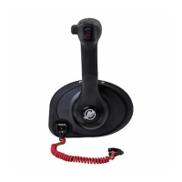
Throttle and Shift Cable Installation
Control Cable Anchor Attaching Location
a - Shift arm
b - Throttle arm
Outboard Models (U.S. and Belgium Models Only)
Starboard Mount Control
Anchor Attaching Location
Shift Cable Throttle Cable
Force outboards, except 9.9 and 15 hp 4 2
Mercury and Mariner outboards ‑ standard rotation models, all models through 300 XS with pull
throttle, includes 1994‑1/2 20/25 hp
4 2
Mercury and Mariner outboards ‑ 18 hp, 20 hp, and 25 hp of U.S. origin, with push throttle cable 4 1
Mercury and Mariner outboards ‑ counterrotation gearcase, all models through 300 XS, unless
listed below
3 2
Mercury and Mariner outboards ‑ standard rotation gearcase, 250 hp/275 hp 3.4L 3 2
Mercury and Mariner outboards ‑ counterrotation gearcase, 250 hp/275 hp 3.4L 4 2
Mercury outboards ‑ standard rotation gearcase, 3.0L EFI, OptiMax S/N 1B752547 and above 4 2
Mercury outboards ‑ counterrotation gearcase, 3.0L EFI, OptiMax S/N 1B752547 and above 4 2
Mercury 3.0L outboards with Torque Master gearcase S/N 1B973743 and below 4 2
Mercury 3.0L outboards with Torque Master II gearcase S/N 1B973744 and above 4 2
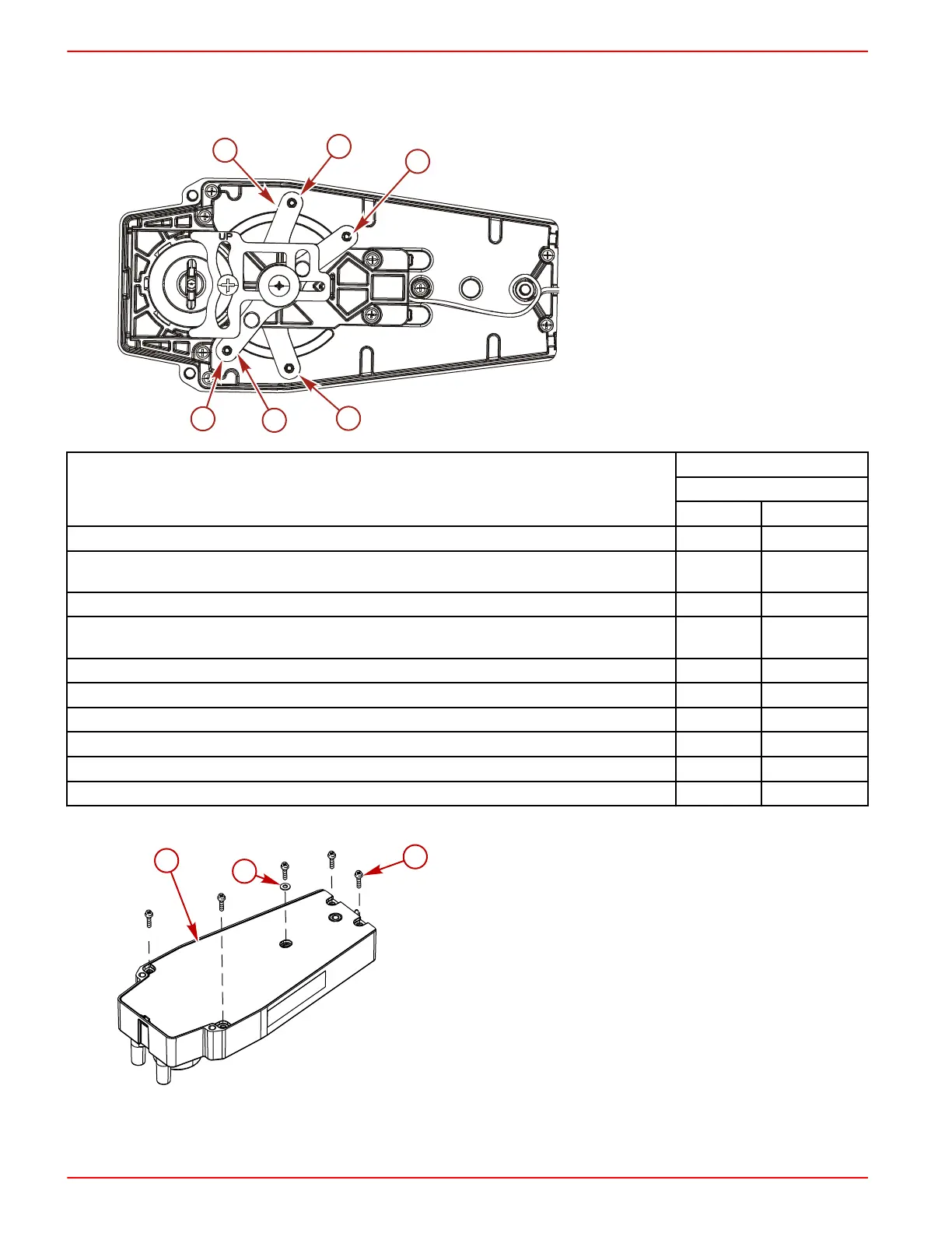
1. Remove the screws securing the back plate to the control module.
a - Back plate
b - Washer
c - Screw (5)
IMPORTANT: Determine the type of drive unit rotation the cable is installed onto. The shift cable must be correctly
installed at the remote control assembly for the appropriate drive unit rotation; standard or counterrotation.
 Loading...