4000 MPC GEN II PISTOL GRIP REMOTE CONTROL INSTALLATION INSTRUCTIONS
90-8M0103111 FEBRUARY 2015 Page 7 / 22
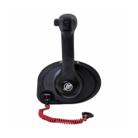
Bezel Installation
Install and secure the bezel to the mounting platform surface. Tighten the bezel mounting screws to the specified torque.
a - Screw (0.250‑20 x 1.750 in.) (3)
b - Washer (3)
c - Nut (0.250‑20) (3)
d - Mounting platform
Description Nm lb‑in. lb‑ft
Bezel mounting screw (3)
Aluminum or fiberglass 5.6 50 –
Plywood 4 35.4 –
NOTE: On some boat installations, it may be helpful to first make the cutout for the remote control using the supplied
template, and route the control cables through the boat before installing the cables to control module.
Selecting and Routing Remote Control Cables
Mercury - Mariner - Force - Mercury MerCruiser
Refer to the Mercury Precision Parts Accessories Guide for the available shift and throttle cables for your application.
IMPORTANT: GEN II throttle and shift cables are required with the GEN II remote controls. The remote control cables must
be the correct length. Sharp bends when the cables are too short result in kinks. Cables that are too long require unnecessary
bends or loops. Both conditions place extra stress on the cables resulting in unfavorable shift and throttle operation. The
minimum bend radius of the remote control cable is 30.5 cm (12 in.). For applications that require smaller than the minimum
radius, multiple bends or lengths longer than 5.5 m (18 ft), Mercury/Quicksilver GEN II Platinum or Premium cables are
required. Refer to the Mercury Precision Parts Accessories Guide.
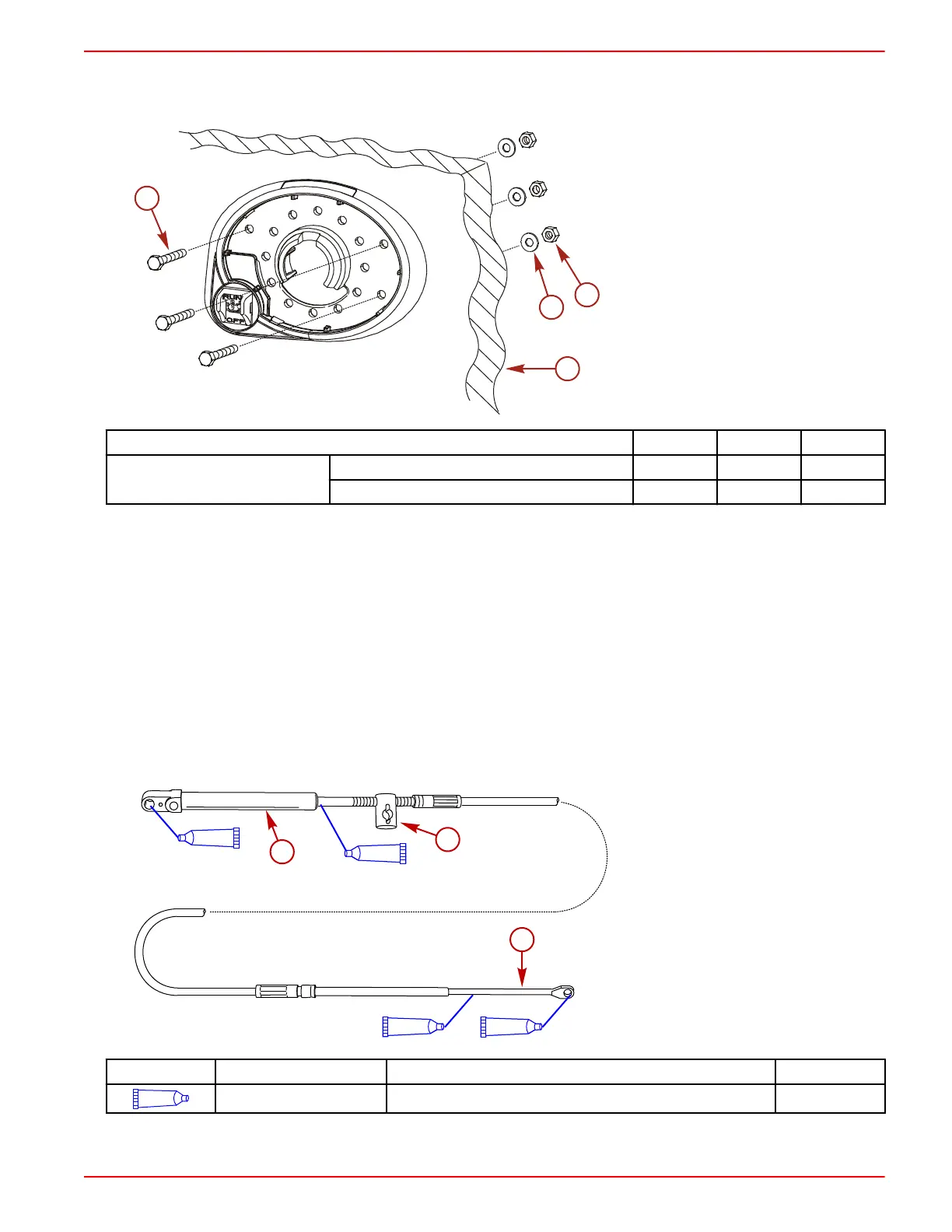
IMPORTANT: Lubricate the shift cable and throttle cable with 2‑4‑C with PTFE on the locations shown in the following
graphic.
a - Remote control end
b - Engine end
c - Adjusting barrel
Tube Ref No. Description Where Used Part No.
95
2-4-C with PTFE Shift cable and throttle cable lubrication points 92-802859A 1
 Loading...