4000 MPC GEN II PISTOL GRIP REMOTE CONTROL INSTALLATION INSTRUCTIONS
Page 6 / 22 90-8M0103111 FEBRUARY 2015
IMPORTANT: When selecting the mounting area for the panel mount remote control, the area located directly behind the
mounting panel must have sufficient clearance for the control module, wiring harness, control cables, and control cable
movement. Refer to the Required Mounting Clearances for GEN II Pistol Grip Fingertip Lock Release Panel Mount Control.
IMPORTANT: Allow sufficient clearance for the control handle movement. Avoid interference with the boat components or
other accessories. Ensure the control handle clears the dash, seats, steering wheel, and any other obstructions.
Bezel Location and Drilling Mounting Area
IMPORTANT: The mounting surface for the bezel should be a flat and ridged platform, preferably constructed with one of the
following: aluminum, fiberglass, or plywood reinforced with fiberglass. One layer of vinyl between the bezel and ridged
mounting platform is acceptable. All foam should be removed between the bezel and the ridged mounting platform. To ensure
a robust installation, the mounting platform must not exceed 2.54 cm (1 in.) thickness.
NOTE: The remote control template supplied with this instruction sheet will allow the installer to rotate and mount the remote
control module in 30° increments. Allow for proper clearance behind the mounting area when selecting the mounting area for
the remote control.
1. Locate the area of the boat where the panel mount remote control is to be mounted. Allow sufficient clearance for the
control handle movement, remote control module, and control cables behind the mounting area.
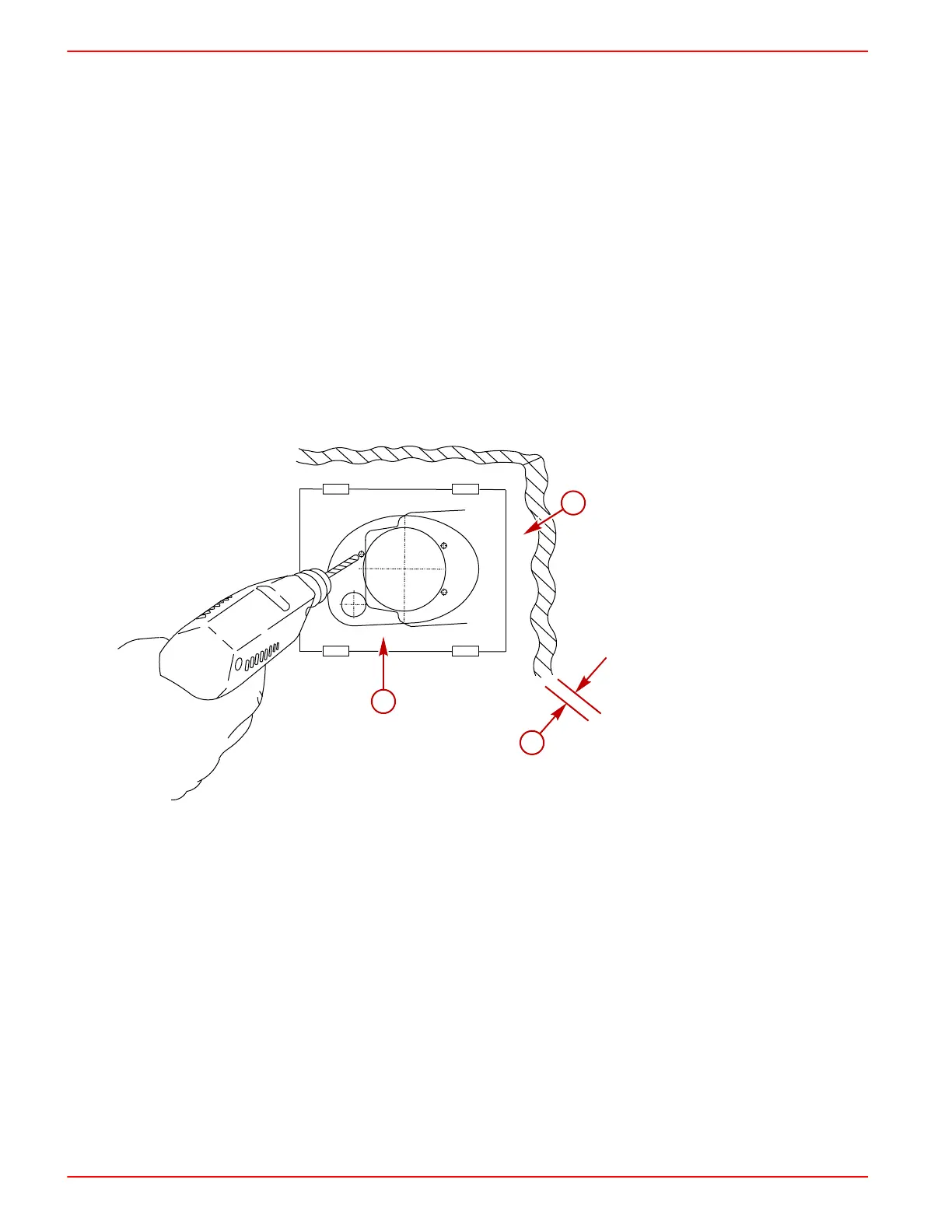
2. Use the template supplied with these instructions and place the template over the mounting platform surface.
3. Secure the template to the mounting platform surface with tape. Cut and drill the mounting platform surface as instructed
on the template.
IMPORTANT: After cutting and drilling the mounting platform, use a suitable tool to remove all of the sharp edges on the
inside and outside of the mounting platform cutout to prevent chafing of the harnesses.
a - Mounting surface
b - Maximum mounting platform
thickness 2.54 cm (1 in.)
c - Template
 Loading...