4000 MPC GEN II PISTOL GRIP REMOTE CONTROL INSTALLATION INSTRUCTIONS
Page 2 / 22 90-8M0103111 FEBRUARY 2015
It is assumed that these personnel are familiar with the installation procedures of these products, or like or similar products
manufactured and marketed by Mercury Marine. Also, that they have been trained in the recommended installation
procedures of these products, which includes the use of mechanics’ common hand tools and the special Mercury Marine or
recommended tools from other suppliers.
We could not possibly know of and advise the marine trade of all conceivable procedures by which an installation might be
performed and of the possible hazards or results of each method. We have not undertaken any such wide evaluation.
Therefore, anyone who uses an installation procedure or tool that is not recommended by the manufacturer must first
completely satisfy himself that neither his nor the product’s safety will be endangered by the installation procedure selected.
All information, illustrations, and specifications contained in this manual are based on the latest product information available
at time of publication. As required, revisions to this manual will be sent to all OEM boat companies.
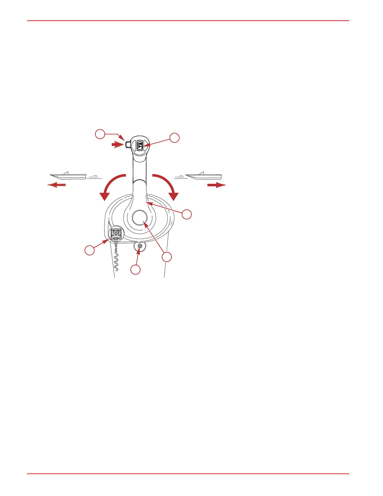
GEN II Pistol Grip with Fingertip Neutral Lock Release Panel Mount Remote
Control Features and Operation
1 - Neutral lock button
2 - Throttle only button
3 - Power trim switch
4 - Lanyard stop switch
5 - Control handle
6 - Control handle friction adjustment nut
1.
Neutral lock button ‑ Prevents unintentional shifting into gear. To shift into gear, press and hold the neutral lock button
and move the control handle out of neutral.
2.
Throttle only button ‑ The throttle only button allows throttle advancement without shifting the engine. The throttle only
button disengages the shifting mechanism from the control handle. The throttle only button can be pressed and held in
only when the remote control handle is in the neutral position. While holding the throttle only button in, move the throttle
handle forward to assist in starting the engine.
3.
Power trim (and trailer MCM only) switch (if equipped) ‑ Used to trim or raise drive unit for trailering, launching,
beaching, or shallow water operation.
4.
Lanyard stop switch (if equipped) ‑ The purpose of a lanyard stop switch is to turn off the engine when the operator
moves far enough away from the operator's position (as in accidental ejection from the operator's position) to activate the
switch. Tiller handle outboards and some remote control units are equipped with a lanyard stop switch. A lanyard stop
switch can be installed as an accessory ‑ generally on the dashboard or side adjacent to the operator's position.
• The lanyard is a cord usually between 122 and 152 cm (4 and 5 feet) in length when stretched out, with an element
on one end made to be inserted into the switch and a snap on the other end for attaching to the operator. The
lanyard is coiled to make its at‑rest condition as short as possible to minimize the likelihood of lanyard entanglement
with nearby objects. Its stretched‑out length is made to minimize the likelihood of accidental activation should the
operator choose to move around in an area close to the normal operator's position. If it is desired to have a shorter
lanyard, wrap the lanyard around the operator's wrist or leg, or tie a knot in the lanyard.
 Loading...