4000 MPC GEN II PISTOL GRIP REMOTE CONTROL INSTALLATION INSTRUCTIONS
Page 20 / 22 90-8M0103111 FEBRUARY 2015
1. Check all fasteners which secure the control housing to the control module, and the control and module to the boat.
Tighten any loose fasteners to the specified torque listed in the installation instructions.
2. Check the control handle retaining screw to ensure that it is tightened to the specified torque. If the screw has been
removed for any reason, Loctite 271 Threadlocker should be applied to the screw threads before installation.
3. Check electrical connections to be sure that they are tight, free of corrosion, and that all harnesses are properly secured
and kept away from water.
4. Inspection and lubrication of the remote control assembly should be performed once each year by your authorized
dealer. Lubrication should also be performed if the remote control is disassembled, or if control operating effort has
increased. Lubricate with 2‑4‑C with PTFE or equivalent.
5. Yearly inspection of the cables for free‑play should coincide with the dealer inspection and lubrication. Cable ends should
be disconnected from both the engine and the control. Cable ends should be manually manipulated to feel for stiffness,
binding, or tightness affecting the cable core. Worn, pinched, or corroded cables should be replaced. Mercury/Quicksilver
GEN II throttle and shift cables are required for use in this remote control.
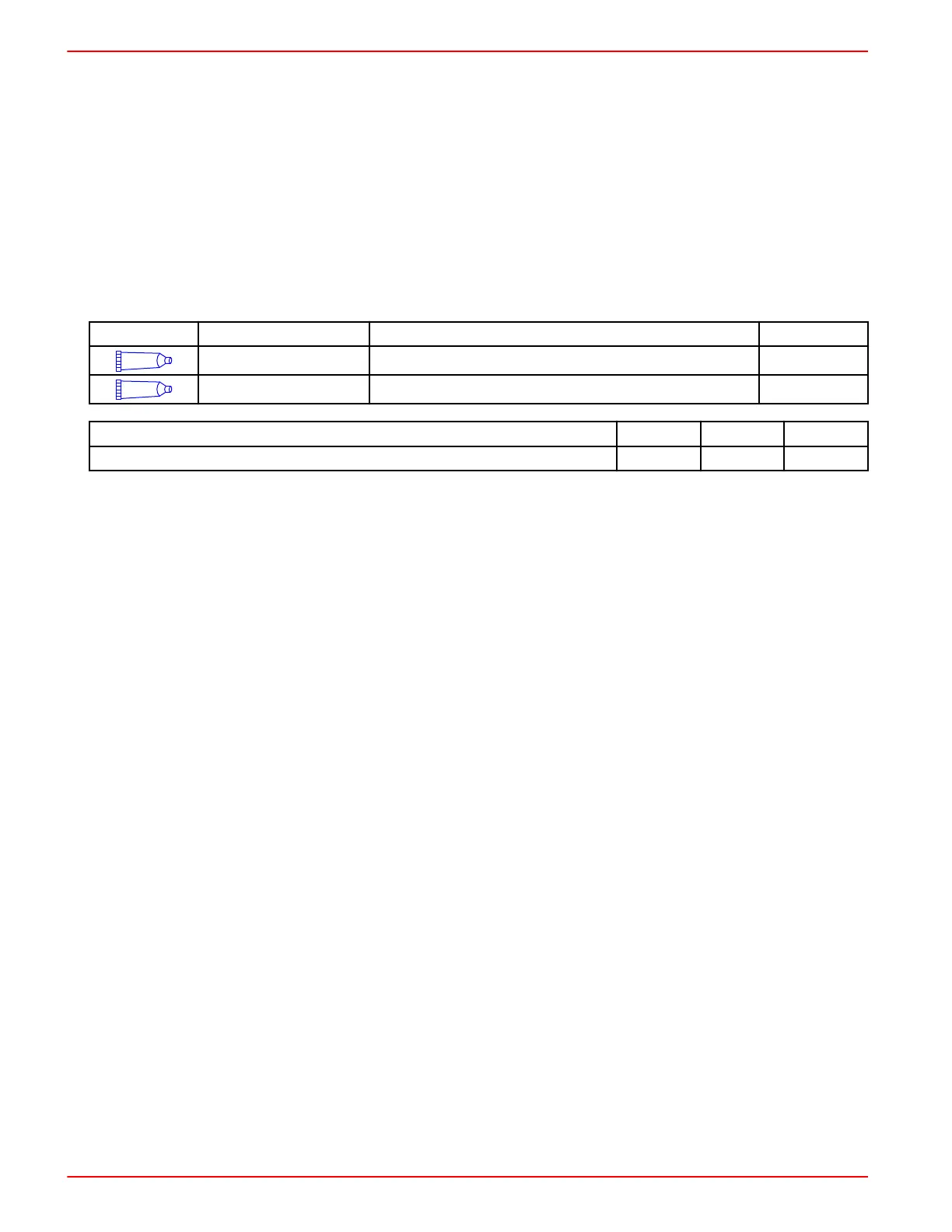
Tube Ref No.
Description Where Used Part No.
7
Loctite 271 Threadlocker Control handle retaining screw threads 92-809819
95
2-4-C with PTFE Remote control internal moving parts and control cable ends 92-802859A 1
Description Nm lb‑in. lb‑ft
Control handle retaining screw 17 150 –
GEN II Series Panel Mount Remote Control Bezel Template
IMPORTANT: Due to printing variables, the image may have changed from the actual size. Check this template with the bezel
before cutting the mounting holes, or use the bezel as a guide to mark the mounting surface.
NOTE: This remote control module can be mounted 30° up or down by using the same bezel mounting location holes. Rotate
only the control module to the desired angle. It may be necessary to secure the bezel with additional wood screws or lag
screws.
1. Drill and cut out the shaded area as indicated.
2. When using wood screws or lag screws, drill to the correct hole diameter for the fastener used. Refer to item a.
 Loading...