4000 MPC GEN II PISTOL GRIP REMOTE CONTROL INSTALLATION INSTRUCTIONS
90-8M0103111 FEBRUARY 2015 Page 13 / 22
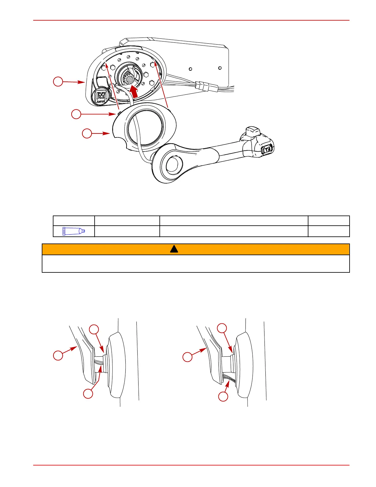
6. Align the tabs on the bezel cover with the slots on the bezel. Snap the bezel cover in place.
a - Bezel
b - Tabs (4)
c - Bezel cover
7. Apply Loctite 271 Threadlocker on the threads of the control handle retaining screw.
NOTE: A new control handle retaining screw has threadlocking compound on the threads. A control handle retaining
screw that was installed and removed must have Loctite 271 Threadlocker applied to the threads.
Tube Ref No.
Description Where Used Part No.
7
Loctite 271 Threadlocker Control handle retaining screw 92-809819
!
WARNING
Improper installation can result in sudden, unexpected loss of throttle and shift control, resulting in serious injury or death.
Install all control components properly.
8. Install the control handle assembly onto the remote control module. Ensure the control handle is in neutral and in the
desired position.
IMPORTANT: Ensure the trim switch wires do not become pinched between the bezel and the control handle during the
installation of the control handle onto the remote control. Failure to ensure the trim switch wires do not become pinched
during the installation of the control handle onto the remote control, may result in the trim switch wires shorting out and
causing a trim system failure.
Incorrect trim switch wire routing
Correct trim switch wire routing
a - Control handle
b - Bezel
c - Trim switch wires
9. Secure the control handle with the retaining screw. Tighten the control handle retaining screw to the specified torque.
 Loading...