GASOLINE STERNDRIVE INSTALLATION MANUAL
Page 136 of 137 90-860172011
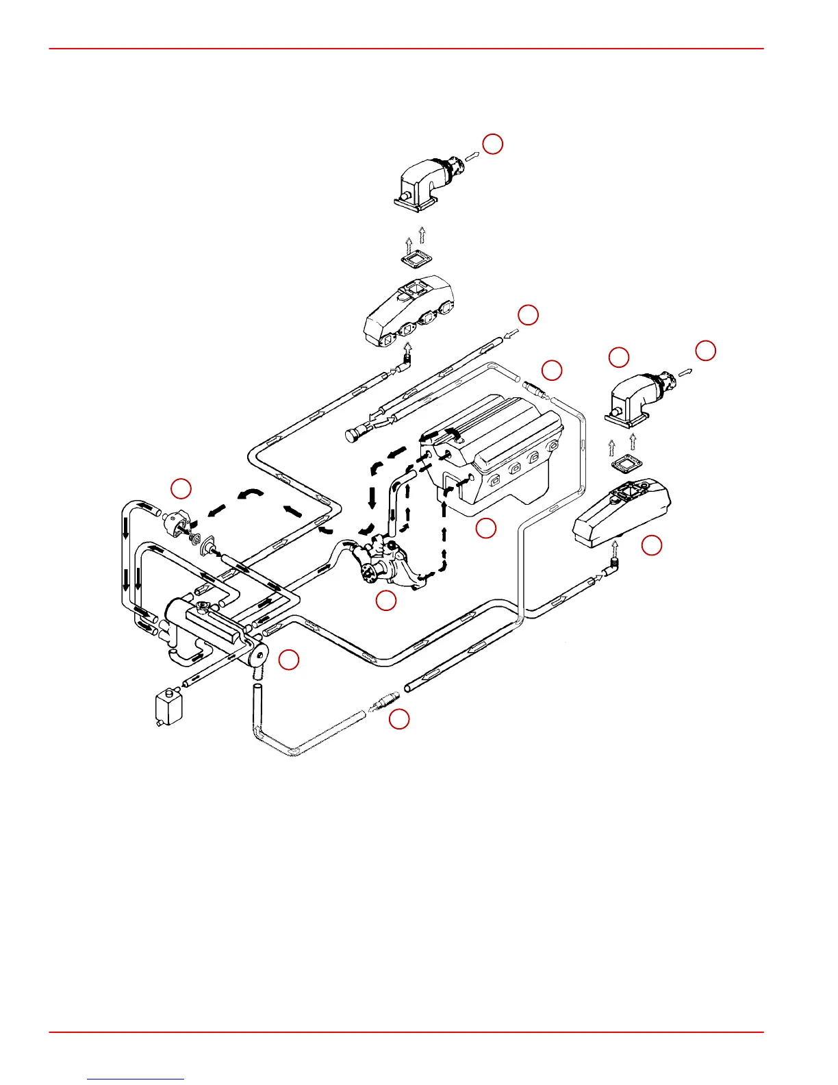
V6 and V8 Engines - Closed Cooled
NOTE: Certain components in the following diagram may look different than on your particu-
lar power package, but the water and coolant flow paths remain similar on all engines.
75005
10
1
2
3
4
5
6
7
8
9
10
1-Seawater Intake (From Sterndrive)
2-Power Steering Cooler
3-Fuel Cooler, If Equipped
4-Heat Exchanger, Typical
5-Thermostat Housing and Cover Assembly
6-Engine Water Circulating Pump
7-Engine Block and Cylinder Head Assembly
8-Exhaust Manifold, Typical
9-Exhaust Elbow Assembly, Typical
10 - Overboard (Water and Exhaust Discharge)

 Loading...


