Copyright Meritor, Inc., 2021Printed in USA
MM-2034 / Issued 02-21
Page 42
7 Assembly
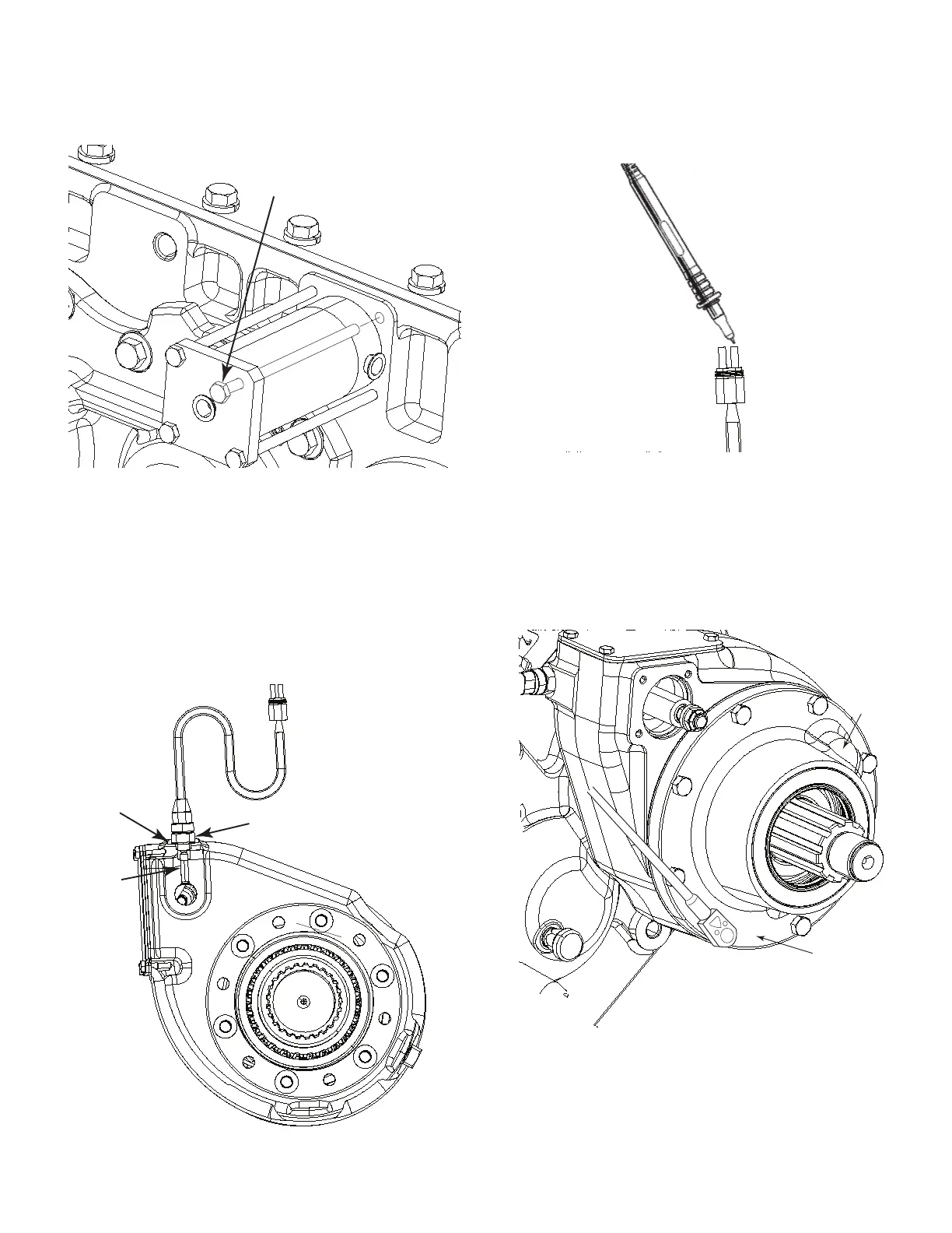
37. Install the shift cylinder cap using Loctite 242 threadlocker on the
threads. Torque to specifi cation. Figure 7.61.
Shift
Cylinder Bolts
4018199a
Figure 7.61
38. Install the front drive engagement indicator switch pin such that
the rounded end of the pin is facing the shift shaft. Then install
the indicator switch using one copper washer. Figure 7.62.
NOTE: It may be necessary to use two washers for correct switch
operation.
4018211a
Copper
Washer
Pin
Indicator
Switch
Figure 7.62
39. Check for continuity across the sensor leads with a continuity
tester. The tester should indicate a closed circuit with air pressure
applied to the air shift cylinder. Figure 7.63.
4018291a
Figure 7.63
40. Install the front output carrier with a new gasket onto the front
output shaft. Align the bearing oil drain with the bottom of the
case. Apply Loctite 272 threadlocker to the bolt threads and
torque to specifi cation. Figure 7.64.
Front
Output
Carrier
Oil
Drain
4018292a
Figure 7.64