E
VISUAL VIEW14.5
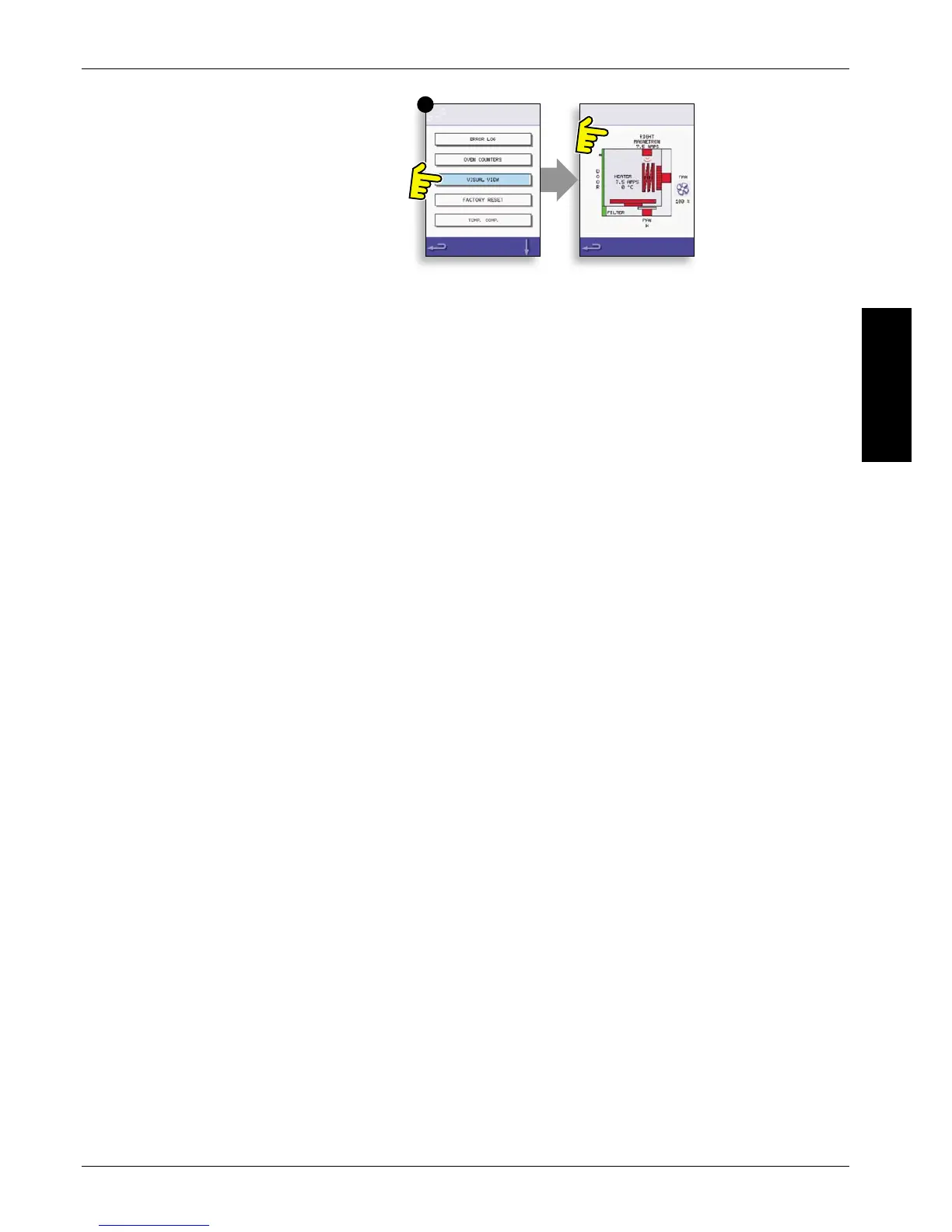
Select VISUAL VIEW (E) to check the main 14.5.1
oven components. Select a component symbol to
switch on (red), select again to increase the level or
turn o (green).
Remove the front air intake lter, the colour 14.5.2
should change from green to red on the display
indicating that the magnetic reed switch circuit for
the air intake lter is operating. Replace the lter
and the colour should change back to green.
Open the oven door and check the colour 14.5.3
changes from green to red on the display to check
the door microswitch/interlock circuit is operating.
Place door spacers onto the oven door (refer to Door
Interlock Adjustment (Testing Components section)
for details), close the door and check the colour on
the display. Green indicates the door adjustment is
ok, red indicates that the Door Interlock Adjustment
procedure must be completed.
With the oven door open; select the 14.5.4
turntable symbol to check it is freely rotating and
stops when deselected.
Select the cooling fan and cycle through the 14.5.5
settings to check it’s operation.
Place a microwave safe container of water 14.5.6
into the oven, close the oven door and select a
magnetron to test the current draw at maximum
output, this will time-out after 30 seconds. Using
heat proof gloves, remove the container and close
the oven door.
Select the Convection Fan and check it is 14.5.7
operating through the dierent fan speed settings
available.
Select the Heating Element, it increases to 14.5.8
maximum temperature then cycles (the Convection
Fan is on by default). Check the cavity temperature
and heater element current draw at maximum are
correct.