35
SC-1
4.1.2 CALIBRATION PROCESS
SC-1 with firmware revision 1.30 or greater have the calibration feature. A video tutorial of
the calibration process is available on metergroup.com/environment/articles/quick-guide-
calibrating-sc-1-porometer. METER has a calibration service to perform maintenance and
calibration on the SC-1. The calibration routine is the same as outlined in this section.
NOTE: For instructions on how to upgrade the SC-1 firmware to the latest version, see Section3.4.
Each sensor head has a default 7-digit calibration number on the sensor head cable tag
and on the calibration certificate. This default calibration number will be applied to each
measurement until a user-initiated calibration is performed. The new calibration number will
be stored and applied to all subsequent measurements until another calibration is done or
the calibration is reset to the default.
If verification (Section4.1.1) indicates that the measurements are inaccurate, use the
following steps to calibrate the SC-1.
1. Allow the SC-1 sensor head, DI water, and calibration plate to come to thermal
equilibrium with the measuring environment.
For example, moving the SC-1 from an air-conditioned environment into field conditions
can take 10 min or more to reach equilibrium. A calibration block or bottle of DI water
that has been kept in a pants pocket or hand for extended periods of time will also need
time to reach equilibrium.
To check for thermal equilibrium, initiate a measurement in Manual mode (Section3.3.2)
or navigate to the Diagnostic screen (Section3.3.1) to monitor temperature readings
until they are steady.
Holding the sensor head in the correct manner during calibration is very important
for maintaining thermal equilibrium. Figure43 illustrates the correct way to hold the
external sensor.
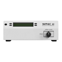
2. Turn on the SC-1 controller.
3. Navigate to the Configuration tab.
4. Select Diagnostics.
5. Check the RH Leaf or RH Filter values.
If the values are above 5% RH, the desiccant is exhausted and must be replaced.
a. Remove the desiccant chamber from the bottom of the leaf clip by unscrewing it
counterclockwise.
b. Discard the exhausted desiccant.
c. Refill the desiccant chamber three-quarters full with fresh desiccant.
d. Replace the desiccant chamber on the sensor head.
6. Press MENU to navigate back to the Configuration tab (Figure44).