3.9 Air/nitrogen connector
■■■■■■■■■■■■■■■■■■■■■■
18
■■■■■■■■
860 KF Thermoprep
3
Screw the second 6.1805.080 FEP tubing (25 cm length) to the gas
inlet (at the rear, labeled 2). Screw the other tubing end on the rear
drying flask to the M6 connector with point marking (see right-hand
arrow).
4
Screw the 6.1805.010 FEP tubing (13 cm length) tightly onto the
remaining M6 connectors of the drying flasks.
The marking Drying flask on the right-hand side of the instrument
displays the diagram for the tubing.
Note
Tighten the screw connections well by hand.
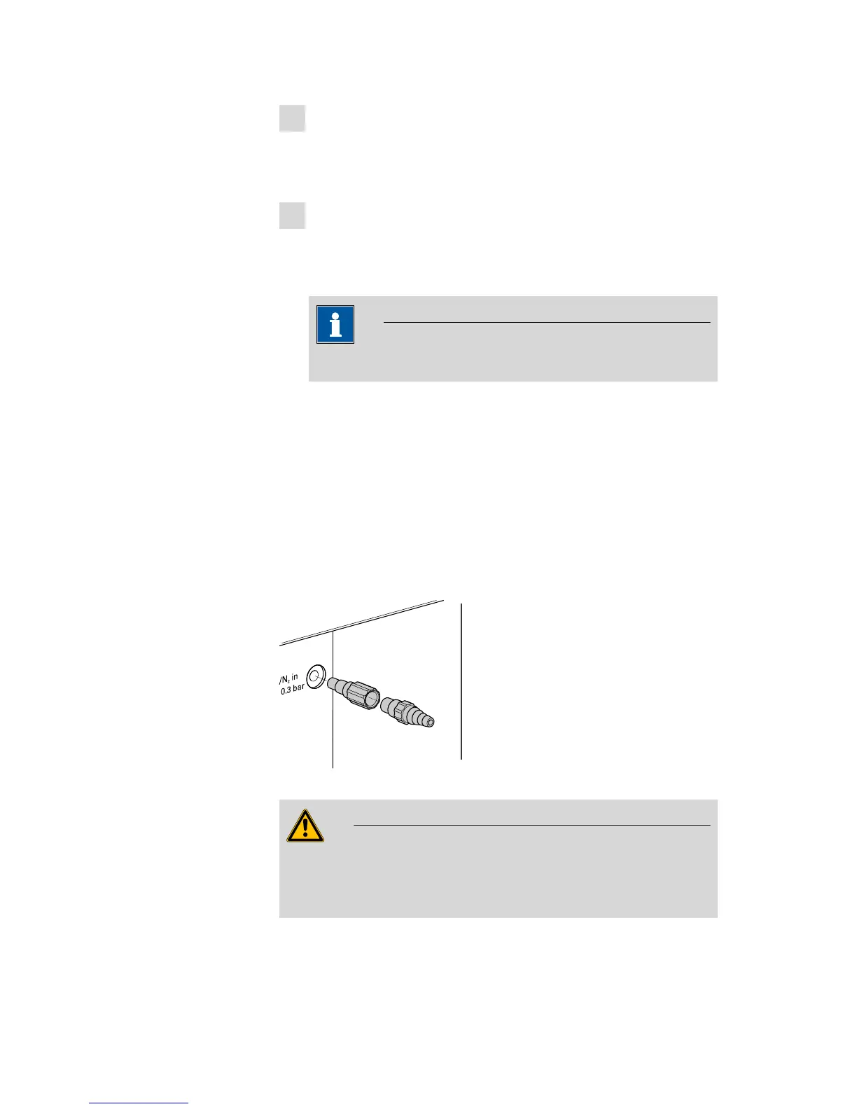
3.9 Air/nitrogen connector
If compressed air, nitrogen or another gas is to be used for transferring or
expelling moisture, then a separate connector is available on the rear of
the instrument.
A tube with M6 thread can be connected directly to the connector Air/N
2
in. Enclosed with the instrument is the 6.1808.040 M6/M8 tubing
adapter for tubing with an M8 thread. The 6.1808.050 M8/tubing
olive can also be put in place in order to connect a simple tubing.
Figure 16 External gas supply connection
Warning
If gas is supplied from a pressure line or a pressure vessel, then it is
imperative that a pressure reduction valve be placed upstream. The gas
pressure may not exceed a maximum overpressure level of 0.3 bar.
 Loading...