Table of figures
■■■■■■■■■■■■■■■■■■■■■■
VI
■■■■■■■■
860 KF Thermoprep
Table of figures
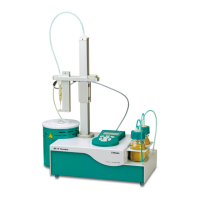
Figure 1 Front 860 KF Thermoprep ................................................................. 6
Figure 2 Rear 860 KF Thermoprep ................................................................... 7
Figure 3 Connecting the mains cable .............................................................. 8
Figure 4 Loosen the adapter ........................................................................... 9
Figure 5 Mounting the guidance rod ............................................................. 10
Figure 6 Mounting tubing ............................................................................. 10
Figure 7 Fix the adapter ................................................................................ 11
Figure 8 Guidance rod mounted ................................................................... 11
Figure 9 Mounting the sample insert ............................................................. 12
Figure 10 Mounting the needles ..................................................................... 13
Figure 11 Mounting the heating tubing (view from rear) ................................. 14
Figure 12 Connecting the heating tubing ........................................................ 15
Figure 13 Mounting the dust filter .................................................................. 16
Figure 14 Preparing the drying flasks ............................................................... 16
Figure 15 Mounting the tubings ..................................................................... 17
Figure 16 External gas supply connection ........................................................ 18
Figure 17 Coulometric KF titration cell ............................................................ 19
Figure 18 Volumetric KF titration cell .............................................................. 20
Figure 19 Mains switch ................................................................................... 22
Figure 20 Keypad and operating unit .............................................................. 22
Figure 21 Main dialog ..................................................................................... 23
Figure 22 Insert the sample vessel into the oven ............................................. 31
Figure 23 Move the guide head down ............................................................ 31
Figure 24 Insert the needle ............................................................................. 32