■■■■■■■■■■■■■■■■■■■■■■
3 Installation
Combustion-IC-System
■■■■■■■■
17
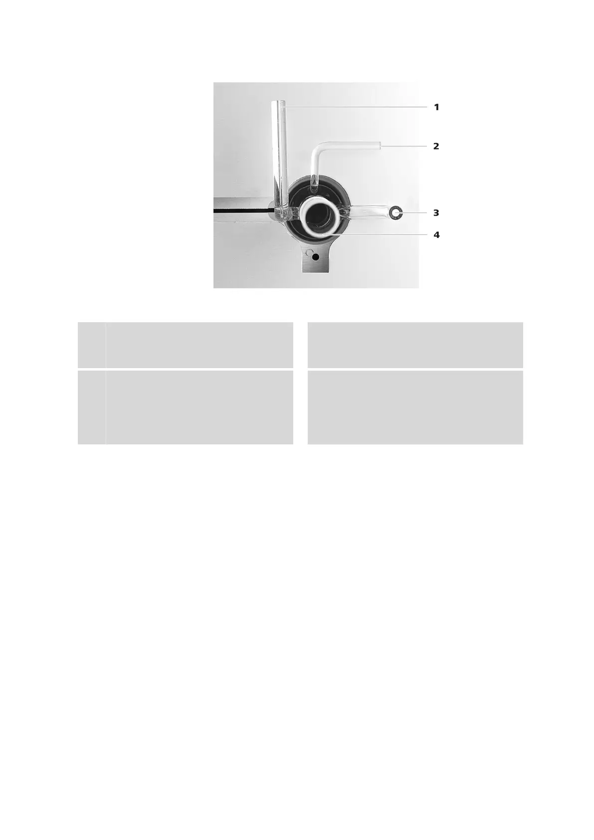
Figure 9 Combustion tube – Inlet
1
Water infeed inlet
Connection for the capillary with the blue
colored sleeve (4-14).
2
Flame sensor connection
Connection for the flame sensor.
3
Oxygen infeed
Connection for the oxygen infeed.
4
Sample inlet
Solid and liquid samples: inlet for sample
boats.
Gaseous samples: connection of the
LPG/GSS module.
■ Plug the capillary into a FAST connector (see Chapter "Replacing
tubing connections" in the Combustion Module operating
instructions).
■ Carefully attach the FAST connector to the connector (9-1).
You can find information on connecting the flame sensor, the oxygen
infeed and the ABD in the Combustion Module (AJ) operating
instructions.