■■■■■■■■■■■■■■■■■■■■■■
3 Installation
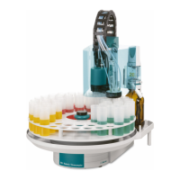
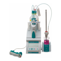
Combustion-IC-System
■■■■■■■■
19
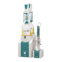
Connecting the capillary for the combustion gases
1
Feeding the capillary into the Combustion Module (AJ)
■ Push the loose end of the PTFE capillary 1/8 / 1/16 ID / 1.5 m
(6.1803.130) (4-8) through the opening in the right-side door of
the 920 Absorber Module.
■ Guide the capillary inside through the round opening in the bot-
tom of the Combustion Module (AJ).
2
Shortening the capillary
Shorten the capillary using the capillary cutter so that it can be con-
nected to the CIC T connector's outlet (10-4) easily.
3
Connecting the capillary
■ Insert the capillary into an angled FAST connector (6.7304.000).
■ Carefully attach the FAST connector to the CIC T connector's out-
let (10-4).
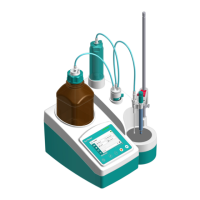
Connecting the capillary for the absorber solution
1
Feeding the capillary into the Combustion Module (AJ)
Guide the loose end of the capillary with the yellow colored sleeve
inside through the round opening at the top in the left-side wall of
the Combustion Module (AJ).
2
Shortening the capillary
Shorten the capillary using the capillary cutter so that it can be con-
nected to the CIC T connector's outlet (10-1) easily.
3
Connecting the capillary
■ Plug the capillary into a straight FAST connector (6.7304.010) (see
Chapter "Replacing tubing connections" in the Combustion Mod-
ule operating instructions).
■ Carefully attach the FAST connector to the CIC T connector's out-
let (10-1).