Table of figures
■■■■■■■■■■■■■■■■■■■■■■
IV
■■■■■■■■
Combustion-IC-System
Table of figures
Figure 1 Detectable elements .......................................................................... 2
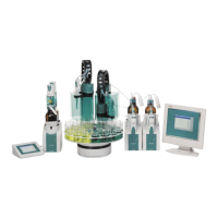
Figure 2 Overview – CIC system ...................................................................... 3
Figure 3 Sequence of the determination ......................................................... 4
Figure 4 Capillaries and tubings in use – Overview .......................................... 9
Figure 5 Connect the Dosino for ultrapure water .......................................... 11
Figure 6 Connect the Dosino for the absorber solution .................................. 12
Figure 7 Connecting the 10-port valve .......................................................... 13
Figure 8 Connecting the 6-port valve ............................................................ 14
Figure 9 Combustion tube – Inlet .................................................................. 17
Figure 10 Combustion tube – Outlet ............................................................... 18
Figure 11 Combustion tube – Inlet .................................................................. 20
Figure 12 Combustion Oven (TEI) – Outlet ...................................................... 21