2.2 Setup
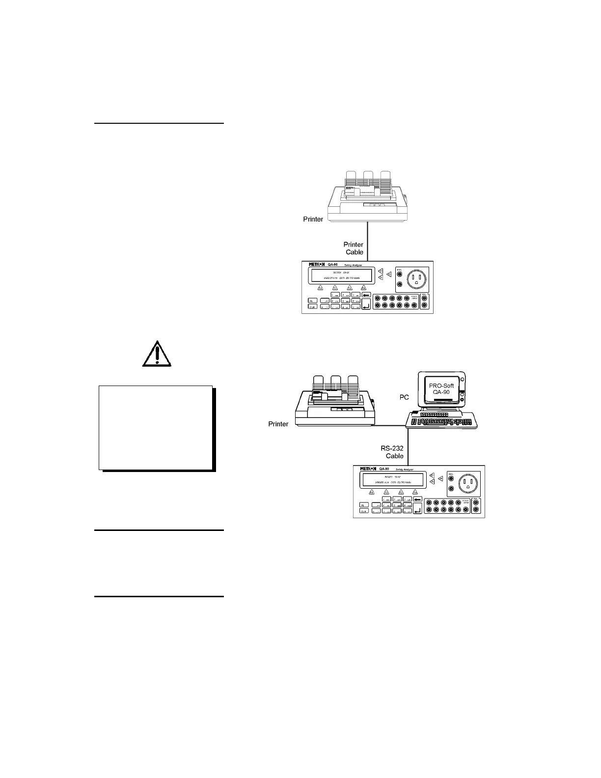
1. Equipment connection is as shown in the typical setup below. At-
tach the printer cable to the 25-pin outlet port.
2. If PRO-Soft QA-90 is being used, attach an RS-232C (null mod-
em/data transfer configured) cable to the 9-pin D-sub outlet port
located at the rear of the QA-90. Do not attach the printer cable
to the QA-90. See below.
2.3 Power
Main On/Off Switch. QA-90 should remain off for at least 5
seconds before switching on again, in order to allow the test circuits
to discharge fully.
2.4 PRO-Soft QA-90
PRO-Soft QA-90 is a front-end test automation and presentation tool
for METRON's QA-90 Electrical Safety Analyzer. It allows you to
conduct the same tests, but by remote control via an IBM-compatible
PC/XT with MS Windows (Version 3.1 or later). Additionally, the
NOTE
Some RS-232C cables are missing
the connection between the se-
venth and the eighth wires in the
cable. The cable may still be called
NULL-modem, but it will not work
with the QA-90. Refer to the PRO-
Soft QA-90 Users Manual for more
information.