4. Example Test Measurements
This chapter contains test examples for the QA-90, illustrating equip-
ment connections for the tests, as well as step-by-step procedures for
obtaining desired test measurements. For more information on safety
testing, and an explanation of protective classes, refer to Appendix A,
IEC 601.1, UL 2601.1 AND VDE 0751 Testing.
4.1 Test Lead Calibration
The self-calibration function of the QA-90 is used to determine test
lead resistance, and for the values to be taken into account during
subsequent testing.
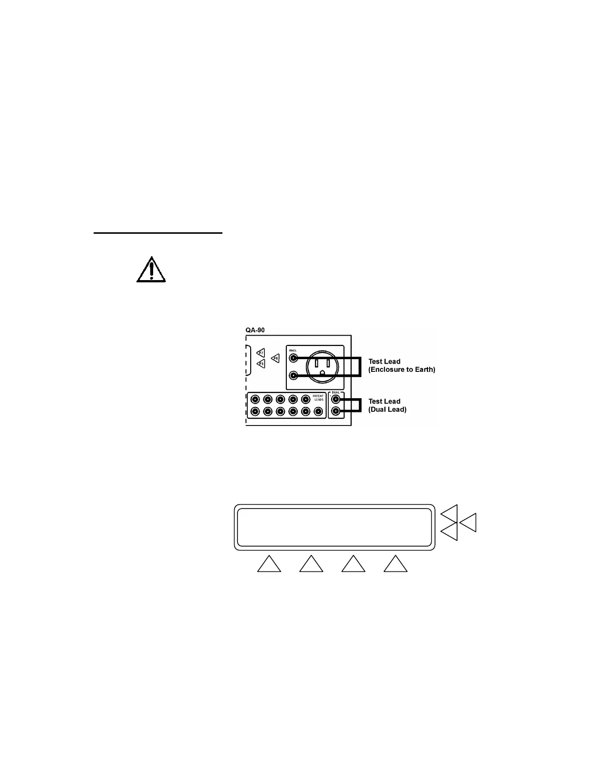
1. Prior to performing self-calibration connect a test lead between
the enclosure and earth connectors, or the dual lead inputs on the
front face of the QA-90 (see below). Disconnect all other leads.
2. Press SETUP (F3) in MAIN MENU.
3. Press CAL (F3) in SYSTEM SETUP.
4. In the SELF CALIBRATION window select an option by press-
ing either Calibrate test lead, enclosure/ground (F6) or Cali-
brate test lead, dual float (F5).
Equipment Code : ...> F7
Sequence Name : ...> F6
Class: CL1 ,0 leads in 0 modules.......> F5
MORE MEMORY SETUP START
F1 F2 F3 F4