5.3 Calibration
1. Enclosure Leakage Current
a. Select Enclosure Leakage Current (F7).
b. Select Normal Condition (F7).
c. Press START (F1) and generate a current (10 µA - 10 mA)
between ENCL. and Chassis. Then, press STOP (F1).
d. Check that both the level of this current, and the readout on
the QA-90 display, are equal.
e. Press GO BACK (F2) twice to go to Manual Test Setup
Window 2.
2. Earth Leakage Current
a. Press Earth Leakage Current (F5).
b. Select Normal Condition (F7).
c. Press START (F1) and generate a current (10 µA - 10 mA)
between EARTH and Chassis. Then, press STOP (F1).
d. Check that both the level of this current, and the readout on
the QA-90 display, are equal.
e. Press GO BACK (F2), then MORE (F1) to advance to Ma-
nual Test Setup Window 3.
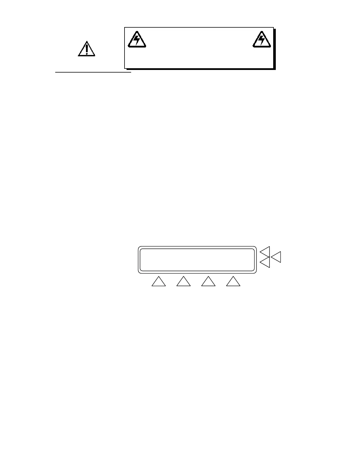
Enclosure Leakage Current .............> F7
Patient Leakage Current AC ............> F6
Patient Leakage Current DC ............> F5
MORE GO BACK MAIN MENU
F1 F2 F3 F4
3. Patient Leakage Current AC
a. Press Patient Leakage Current AC (F6).
b. Select Normal Condition (F7).
c. Press the PL key on the keypad to ensure that the module
with Patient Leads 1-10 (white leads) is active. If not, press
PREV (F3) or NEXT (F4) so that it is active.
d. Press GO BACK (F2) to return to the test window, then
press START (F1).
WARNING!
HIGH VOLTAGES ARE CAPABLE
OF CAUSING DEATH!
USE EXTREME CAUTION WHEN PERFORMING TESTS AND CA-
LIBRATION. USE ONLY INSULATED TOOLS WHEN THE UNIT IS
PLUGGED IN, AND THE CASE HOUSING IS OFF.