1. GENERAL
1.1 Scope of the Manual
This instruction manual contains important information
regarding the installation, operation and maintenance of
the Valvcon V-Series electric actuator. Please read these
instructions carefully and save them for future reference.
1.2 Actuator Markings
WARNING
AS THE USE OF THE ACTUATOR IS APPLICATION SPECIFIC, A
NUMBER OF FACTORS SHOULD BE TAKEN INTO ACCOUNT
WHEN SELECTING AN ACTUATOR FOR A GIVEN APPLICATION.
THEREFORE, SOME OF THE SITUATIONS IN WHICH THE ACTUATORS
ARE USED ARE OUTSIDE THE SCOPE OF THIS MANUAL. IF YOU
HAVE ANY QUESTIONS CONCERNING THE USE, APPLICATION OR
COMPATIBILITY OF THE ACTUATOR WITH THE INTENDED SERVICE,
CONTACT METSO FOR MORE INFORMATION.
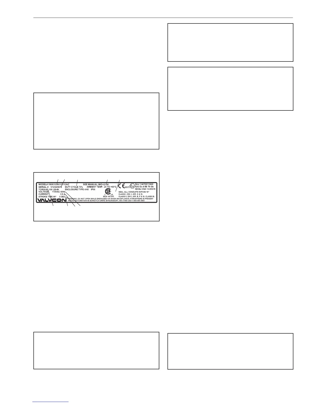
The actuator has an identication label attached to the
base casting (see Figure 1).
( 1 )
( 2 )
( 7 )
( 8 )
( 9 )
( 3 )
( 5 )
( 6 )
( 4 )
Figure 1 Identication Plate
Identication label markings:
1. Model number
2. Serial number
3. Maximum output torque
4. Voltage
5. Current draw (full-load running)
6. Cycle time
7. Duty cycle
8. Applicable manual
9. Certications marking
1.3 Saftey Precautions
WARNING
DO NOT EXCEED THE ACTUATOR PERFORMANCE LIMITATIONS!
EXCEEDING THE TORQUE LIMITATIONS MARKED ON THE ACTUATOR
IDENTIFICATION LABEL MAY CAUSE DAMAGE TO THE ACTUATOR
AND/OR FINAL DRIVE ELEMENT.
WARNING
DO NOT EXCEED THE ACTUATOR ELECTRICAL LIMITATIONS!
EXCEEDING THE ELECTRICAL LIMITATIONS MARKED ON THE
ACTUATOR IDENTIFICATION LABEL MAY CAUSE DAMAGE TO THE
ACTUATOR AND/OR PERSONAL INJURY.
WARNING
BEWARE OF MOVEMENT OF THE FINAL DRIVE ELEMENT AND ANY
LINKAGE BETWEEN IT AND THE ACTUATOR!
KEEP HANDS, OTHER PARTS OF THE BODY, TOOLS AND OTHER
OBJECTS OUT OF THE WAY OF MOVING PARTS. FAILURE TO DO THIS
MAY RESULT IN DAMAGE OR PERSONAL INJURY!
2. TRANSPORTATION AND STORAGE
Check the actuator and any accompanying devices for any
damage that may have occurred during transport.
Store the actuator carefully. Storage indoors in a dry place is
recommended.
Move the actuator to its intended location just before
installation.
The actuator is usually shipped in the full clockwise,
(typically closed) position.
If the actuator(s) will be stored for a period longer than 90
days, follow the recommendations in IMO-S2 to maintain
the actuator’s integrity.
3. GENERAL INSTALLATION
INFORMATION
3.1 Description of Control Board P/N
VC002975 for Modulating Applications
The Control Board connects to the Motor Board with a 10
position plug-in connector and 3 mounting screws that
are captured in the board. The Control Board allows the
actuator to modulate (change position) in response to a
change in an analog control signal. The input control signal
may be either current, such as 4-20 mA, or voltage such
as 0-10 VDC, or 2-10 VDC. The control board also features
analog position feedback, signal fail options, speed control,
locked rotor/stall protection, simple push button set-up,
and auto calibration.
WARNING
DANGEROUS VOLTAGES ARE PRESENT INSIDE THE ACTUATOR
COVER UNLESS THE POWER SUPPLY TO THE ACTUATOR HAS BEEN
SHUT OFF OR DISCONNECTED. USE EXTREME CAUTION WHENEVER
WORKING ON THE ACTUATOR WITH THE COVER REMOVED.

 Loading...


