1. Turn the Mode Selector Dial to [CAL] and press [ENTER]
for 2 seconds. ([CAL] LED may begin to ash)
2. Using the CW pushbutton, drive the actuator to the full
clockwise position. (as viewed from above)
• If the [CAL] LED is ashing, potentiometer
calibration is required; proceed to step 3 below.
• If the [CAL] LED remains on, calibration is not
required; proceed to Setting Zero and Span
Positions section below.
3. Loosen the set screw in the larger plastic gear with a
1/16” hex wrench.
4. Rotate the gear until the LED remains on constantly;
hold the gear in place and tighten the set screw. Ensure
that the LED remains on after the set screw is tightened.
Note: The LED assists the user in locating the proper
calibration window; it will ash faster as you approach
the calibration window and slower as you move away
from it.
5. Press the [ENTER] button to save the potentiometer
setting.
3.4.3 Setting ZERO and SPAN positions
• Setting Zero and Span Positions Once potentiometer
calibration has been conrmed, set the desired end of
travel positions. Make certain that the limit switch cams
are set beyond the desired range for the Zero and Span
positions.
Zero and Span may be set at any position between 0
degrees and 94 degrees of travel. Zero or Span may
be either clockwise or counter-clockwise and may be
set to either a high value or low value control signal.
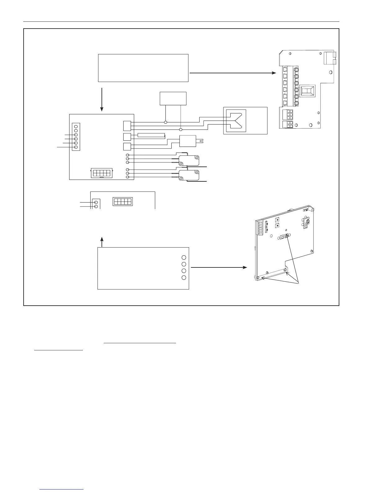
Wiring Diagram – Modulating Applications
(Motor Board and Optional Control Board Installed)
CAUTION: DOUBLE POLE/NEUTRAL FUSING!
MOTOR BOARD WIRING
WITH CONTROL BOARD INSTALLED
TERMINAL 2 AC COMMON
TERMINAL 1 AC HOT
CONTROL BOARD WIRING
TERMINAL A INPUT SIGNAL –> +
TERMINAL B INPUT SIGNAL –>
–
TERMINAL C FEEDBACK –> +
TERMINAL D FEEDBACK –>
–
TERMINAL E No Connection
Motor Board
Control Board P/N VC002975
Mounting Screws
Motor
Board
Control
Board
J3
FROM MOTOR BOARD
TB1
TB1
MOTOR
CAPACITOR
BRAKE SOLENOID
CLOCKWISE (BOTTOM)
LIMIT SWITCH
COUNTER-CLOCKWISE (UPPER)
LIMIT SWITCH
E10
E11
E12
E13
E14
E15
6
5
4
3
2
1
J4
TO CONTROL BOARD
MOTOR
CONNECTOR
HEATER
OPTION
CONNECTOR
BRAKE
OPTION
CONNECTOR
J2
J3
J1
POSITION FEEDBACK POT
CCW RED
RET BLACK
CW WHITE
HEATER
BROWN
RED
ORANGE
GRAY
VIOLET
BLUE
COM
NO
NC
COM
NO
NC
NO CONNECT
NO CONNECT
AC COMMON
AC HOT
INPUT +
INPUT –
FEEDBACK +
FEEDBACK –
RET. GREEN
SIG. BLACK
+5V RED
101857
Figure 3

 Loading...


