3.2 Operating Modes
The Control Board has ve operating modes. Run, Manual,
Set Span, Set Zero and CAL (calibrate). A rotary “Mode
Selector Dial” on the Control Board allows the user to
change the operating mode. To change mode, turn the
rotary selector knob with ngers or a small screwdriver.
Five LED indicators around the knob correspond to one of
the ve modes. When the Control Board mode dial is set to
any mode, the corresponding LED turns on, indicating the
mode is selected.
• Run mode is the basic operating mode. The actuator will
respond to a command control signal which is supplied
to terminal A and terminal B on the Control Board.
• Manual mode permits the user to override the control
signal and drive the actuator by using the [CW] and
[CCW] push buttons. In Manual mode the actuator will
not travel beyond the saved settings for the Zero and
Span stop positions.
• Set Span mode permits the user to precisely
correlatethe end of span travel stop with a
corresponding control signal value. Typically, the Span
position is the fully counter-clockwise position and
maximum control signal value, but Span may be set at
any position or signal value.
• Set Zero mode permits the user to precisely correlate
the opposite end of travel stop position with a
corresponding control signal value. The Zero position
is typically the fully clockwise position and minimum
control signal value, but Zero may be set at any position
or signal value.
• Cal mode allows the user to automatically calibrate the
position tracking potentiometer without the use of an
ohmmeter or other electronic instruments.
3.2.1 Features, Settings and Controls
The control board is designed to be easy to use and hard to
break. Set Up is push button simple and takes one minute!
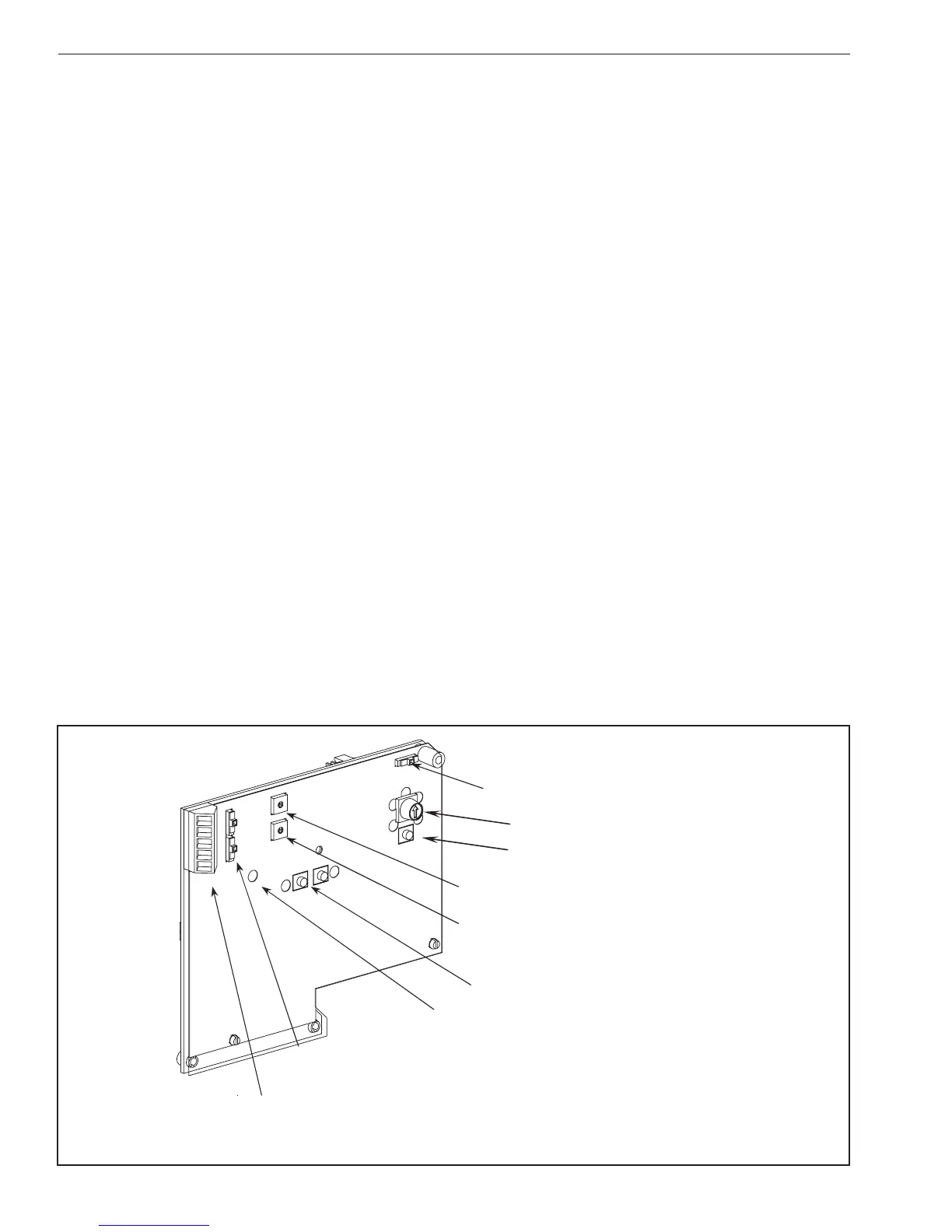
See (Figure 2) for callouts.
• Enter is located directly below the mode selector
and permits the user to activate modes and conrm
settings by pressing the [ENTER] button.
• Control Signal Selection The board can accept either
current or voltage control signals. Make sure the Input
Signal Select switch is correctly positioned for the
input control signal.
• Feedback Signal Selection The board provides a
feedback signal indicating actuator output position.
This signal can be either current or voltage. Make
sure the Feedback Signal Select switch is correctly
positioned for the desired feedback signal. If the
feedback signal is not used, the switch may be left in
either position.
• Control Fail Position In the event that the control
signal to the actuator is lost and power is still applied,
the Signal Fail Position Selector Switch on the Control
Board provides for the actuator to remain at its
LAST (current) position or drive the actuator to the
“ZERO” position. The actuator will maintain the LAST
position or Zero position until a control signal returns
Control Fail Position Switch
Mode Selector Dial
[Enter]
Speed Control Dial
Deadband Adjust Dial
[CW] and [CCW] Push Buttons
Stall LED Alarm
Input Signal & Feedback Signal Switches
Control Signal Input & Feedback Output Terminals
Figure 2
 Loading...


