2. Install the override shaft on the square motor shaft; if
the actuator is equipped with a handwheel, install the
bottom piece of the “two-piece” shaft on the motor
shaft and then install the top piece of the shaft onto
the bottom piece of the shaft.
3. Align cover so that the override shaft will pass through
the override bushing and carefully push it down so that
the cover ange contacts the base ange.
4. Once the cover is properly seated, tighten the screws to
secure the cover; a cross pattern is recommended for
uniform distribution of load.
5. If the position indicator is not seated to the output/cam
shaft, turn until it drops into place in order to ensure
accurate visual position indication.
3.5 Board Installation
WARNING
DANGEROUS VOLTAGES ARE PRESENT INSIDE THE ACTUATOR
COVER UNLESS THE POWER SUPPLY TO THE ACTUATOR HAS BEEN
SHUT OFF OR DISCONNECTED. USE EXTREME CAUTION WHENEVER
WORKING ON THE ACTUATOR WITH THE COVER REMOVED.
3.5.1 Tools Required
• Philips Screwdriver
• Hex wrench, 1/16” (supplied with kit)
• Wrench/Nut driver, 1/2”
3.5.2 Installation Instructions
!Disconnect Power!
1. Remove and discard the screw that secures the Motor
Board to the upper bracket. (See Figure 4)
2. Remove 1/2” locking nut from potentiometer (Pot) shaft
and insert pot shaft up through hole in upper support
bracket. Align locking tab and tighten the locking nut
on pot shaft.
3. Plug Pot connector into the 3-Pin connector on the
front of Control Board. Plug Control Board into the
Motor Board via the 10-pin connector. (Note that the
pot wires should be between the two boards)
4. Secure Control Board to Upper and Lower Support
Brackets with the 3 mounting screws. (Note that the 1”
screw goes in the upper-most mounting hole)
5. Place small (20-tooth) gear on Pot shaft and tighten.
Place spacers on Camshaft then place large (60-tooth)
gear on Camshaft. Properly positioned, gears should
mesh evenly.
6. Supply power to terminal 1 and terminal 2, only. (Ax
“No Connect” label; see Figure 4)
Refer to Section 3.4 for Set Up and Calibration
Procedures.
4. VSERIES STANDARD OPTIONS
All V-Series options are designed to be easily installed in the
eld. Options for all standard V-Series actuators are universal
and completely interchangeable with each enclosure size.
For additional V-Series Options, see (Table 3). Voltage is not
eld changeable.
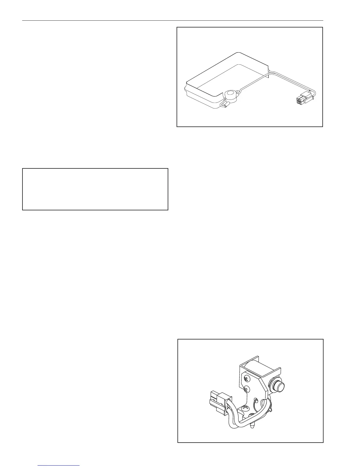
4.1 Option “H” – Tropical Heater and
Thermostat P/N VC099716, VC099723
The tropical heater and thermostat option is a self-adhesive,
resistance heater strip which is applied to the primary
gearbox. It installs with a plug-in connector and is
recommended in high-humidity applications. The tropical
heater option is also recommended in installations that
experience wide temperature swings in order to evaporate
any condensation. Thermostat is pre-set to activate at or
below 90˚F (32˚C) and deactivate at or above 110˚F (43˚C).
The tropical heater draws 15 watts at 115 VAC; 40 watts at
230 VAC (see IMO-I9500 for additional reference).
Option “H” Tropical Heater and Thermostat
Option “T” Standard Heater and Thermostat
Figure 5
Figure 6
Option ”K” - Mechanical Brake

 Loading...


