The Control Board features full reverse acting set up,
requiring no wiring changes. See below for simple Set
Zero and Set Span procedures.
* For 180˚ Rotation order Option Kit P/N VC099180 to
replace 90˚ Potentiometer and Cam Gears.
For 270˚ Rotation order Option Kit P/N VC099270 to
replace 90˚ Potentiometer and Cam Gears.
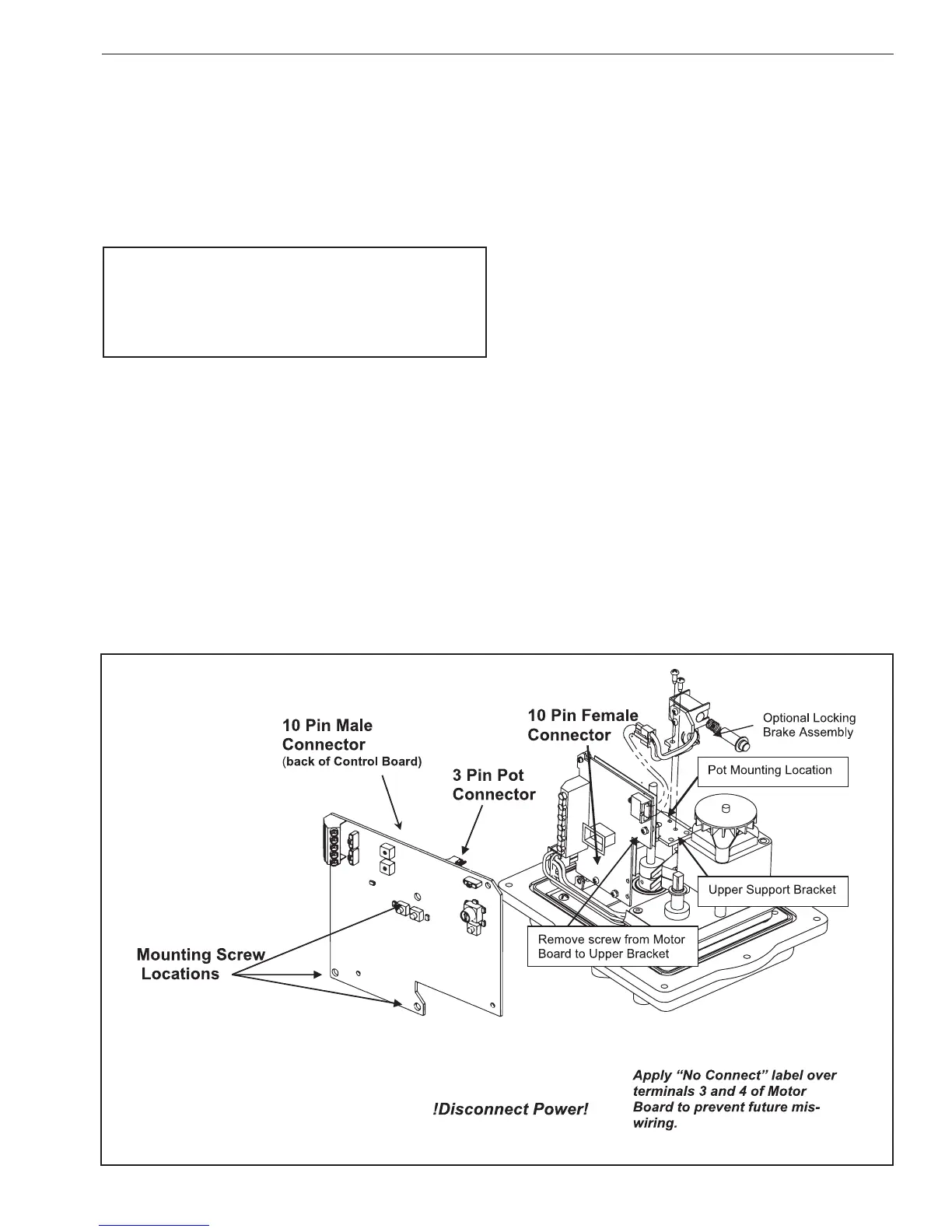
WARNING
WHEN CONTROL BOARD IS INSTALLED, POWER TO TERMINAL 3
OR TO TERMINAL 4 WILL DAMAGE ELECTRONIC CIRCUIT BOARDS.
POWER TERMINALS 1 AND 2; USE CW CLOCKWISE AND CCW
COUNTERCLOCKWISE BUTTONS TO DRIVE ACTUATOR.
Set Zero:
1. Turn the Mode Selector Dial to [ZERO] and press
[ENTER] for 2 seconds. The Zero LED will begin to ash.
2. Drive the actuator to desired minimum signal position
using the CW or CCW pushbutton. If the “STALL” LED
begins to ash; check to see if the limit switch cam is
preventing actuator from reaching desired end-oftravel.
If necessary back the cam o so that it will trip the switch
slightly beyond the desired end-of-travel.
3. Apply input control signal, (i.e. 4 mA).
4. Press the [ENTER] button to save the Zero setting.
Set Span:
1. Turn the Mode Selector Dial to [SPAN] and press
[ENTER] for 2 seconds. The Span LED will begin to ash.
2. Drive the actuator to desired maximum signal position
using the CW or CCW pushbutton. If the “STALL” LED
begins to ash; check to see if the limit switch cam is
preventing actuator from reaching desired end-of-
travel. If necessary back the cam o so that it will trip
the switch slightly beyond the desired end-of-travel.
3. Apply input control signal, (i.e. 20 mA).
4. Press the [ENTER] button to save the Span setting.
Verify Zero and Span Settings:
1. Turn the Mode Selector Dial to [RUN].
2. Apply various control signals to verify operation.
3. Replace actuator cover.
3.4.4 Proper Actuator Cover Installation
1. Remove the override shaft from the actuator cover
bushing; if the actuator is equipped with a handwheel,
remove the handwheel before removing the top piece
of the “two-piece” shaft from the cover bushing.
 Loading...


