HygroCal100 User’s Manual
4
97500 Issue 3, January 2018
INSTALLATION
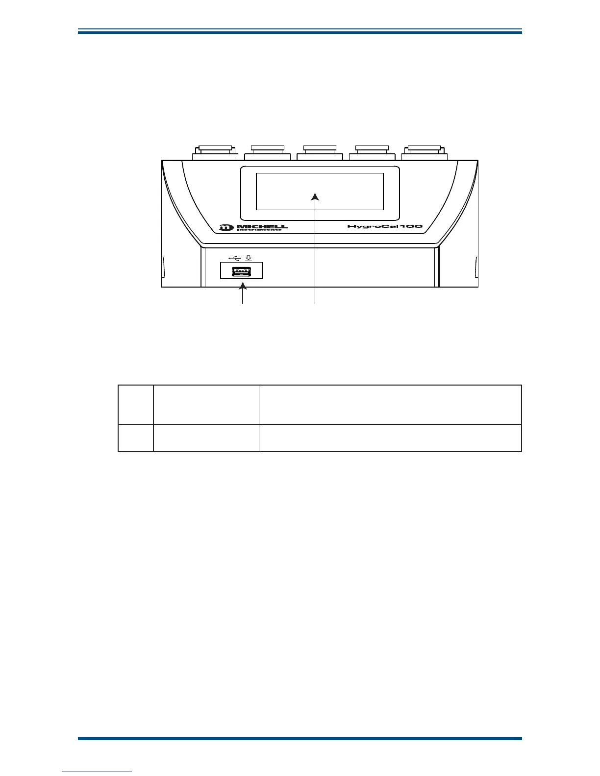
2.3 Exterior Layout
The controls, indicators and connectors associated with the HygroCal100 are located on
the front, top and rear panels of the device.
Front Panel
1 2
Figure 1
Front Panel
1 USB port
Accepts a USB memory device for the transfer of logged
data (see Section 3.4.4.4 for instructions on how to
download logged data).
2 Touch screen display
Displays measured readings and enables the user to
control the operation of the chamber.