These tasks should only be undertaken by qualifi ed personnel.
Connections to the rear panel of the chamber are explained in the following sections:
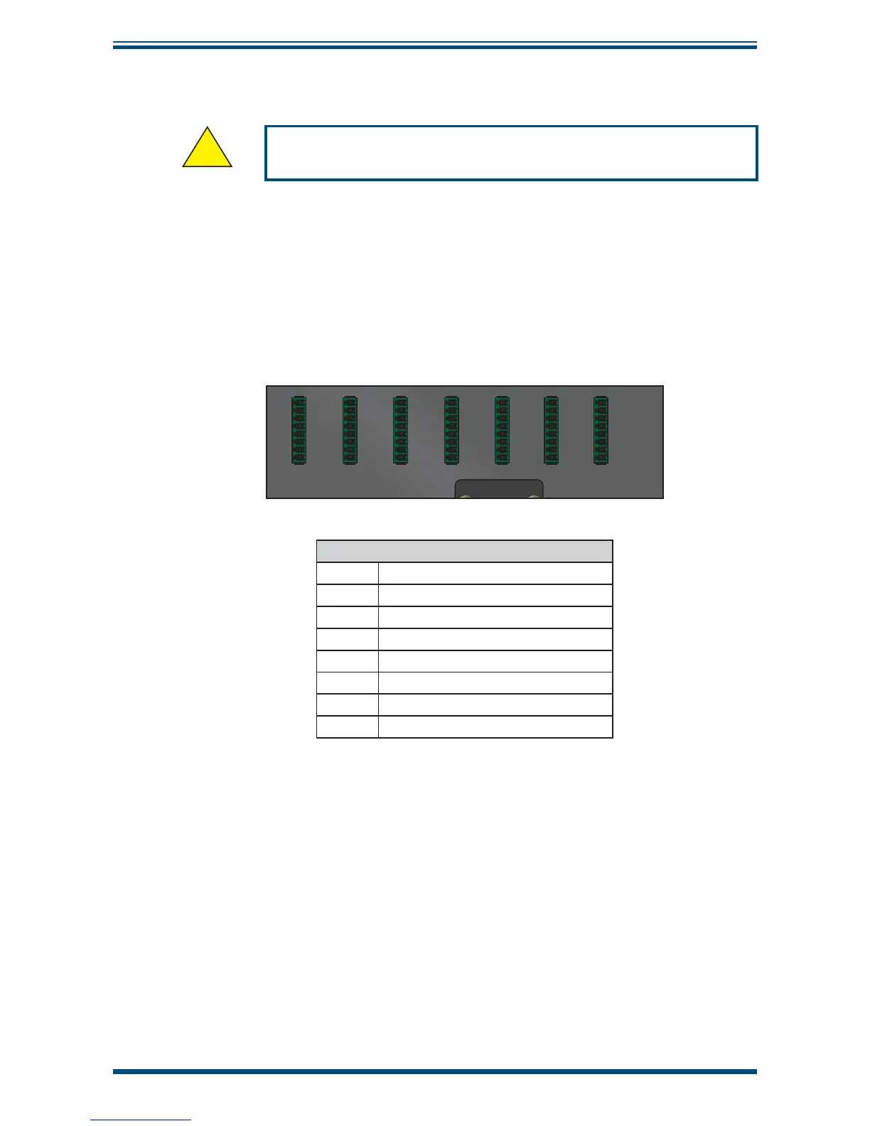
2.4.1 Probe Input Connections
Seven 8-pin connectors are provided to allow connection of probes under test. Probes
with a voltage or current input can be connected.
1234567
1
2
3
4
5
6
7
8
1
2
3
4
5
6
7
8
1
2
3
4
5
6
7
8
1
2
3
4
5
6
7
8
1
2
3
4
5
6
7
8
1
2
3
4
5
6
7
8
1
2
3
4
5
6
7
8
Probe Input Connector Pins
1 DC Supply +15 V / +24 V *
2 Ground
3 RH voltage input
4 Temperature voltage input
5 RH current input
6 Temperature current input
7 Not connected
8 Not connected
* Pin 1 provides +24 V when the mains power adaptor is connected,
or +15 V when running on internal battery power
Figure 4
Probe Input Connections