HygroCal100 User’s Manual
6
97500 Issue 3, January 2018
INSTALLATION
Rear Panel
1
42 3
1
2
3
4
5
6
7
8
1 2 34 567
1
2
3
4
5
6
7
8
1
2
3
4
5
6
7
8
1
2
3
4
5
6
7
8
1
2
3
4
5
6
7
8
1
2
3
4
5
6
7
8
1
2
3
4
5
6
7
8
1
2
3
4
5
6
7
8
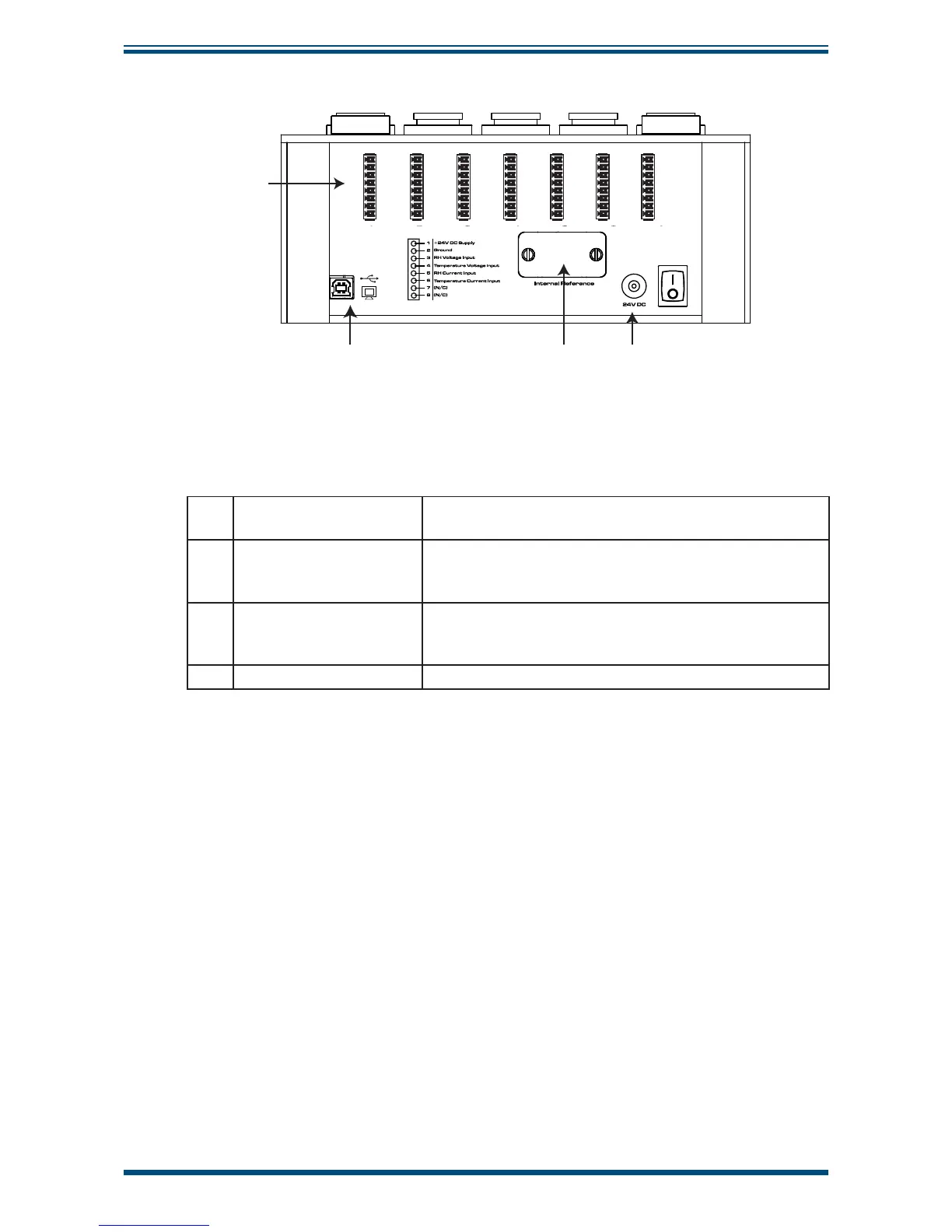
Figure 3
Rear Panel
1 Probe input connections
Connections for probes under test (see Section 2.5.1 for
instructions on how to connect probes).
2
USB communications
port
Allows the HygroCal to be connected to a PC, outputting
the relative humidity and temperature values of both the
reference probes and the probes under test.
3 Service access port
Remove for replacement of HS3 control probe (see
Section 4.3 for instructions on how to replace the control
probe).
4 Power adaptor input 24 V DC input.