Page 18
Mounting
optoCONTROL CLS-K
4.2 Mounting Fiber Optics and Power Supply
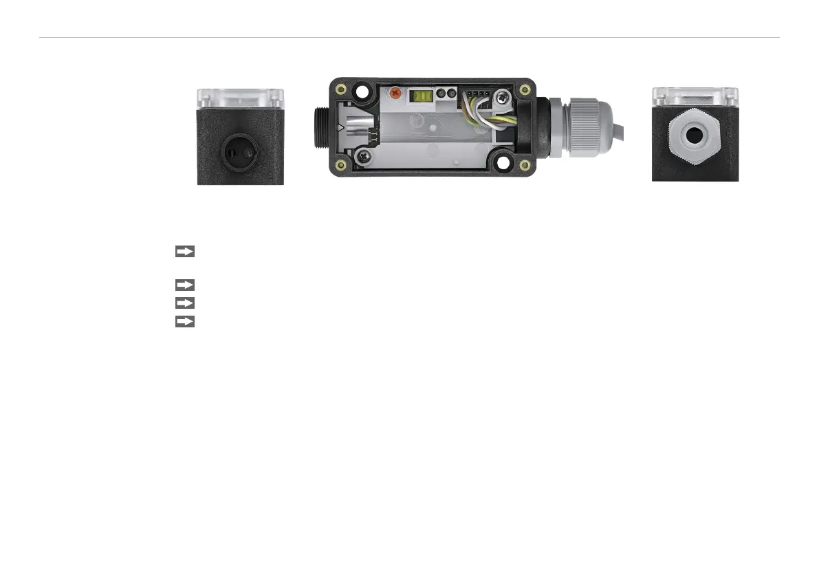
Fig. 4 Connection
fiber optics
Fig. 5 Model optoCONTROL CLS-K-10 with removed
cover
Fig. 6 Connection power
supply
Remove the cover of the amplifier, see Fig. 5 and install the amplifier in accordance with the provided
mounting holes on the housing.
Connect the amplifier in accordance to the pin assignment
1, see Chap. 5.1
, see Chap. 5.1.
Mount the fiber optics to the amplifier, see Fig. 4 and lock it with the cap nut, see Fig. 7.
Attach the probe or the probes of the fiber optics in the required position to the target.
i
Consider here background reflections!
1) The models CLS-K-11, -20, -30, -31, -40, -50, -51, -60, -63, -65 are supplied with screw terminals, see Chap.
2.5. The models CLS-K-10 and CLS-K-61 are delivered with power supply cable.

 Loading...

