ZLR964222L Line Module User Guide
9
Microsemi Corporation Confidential and Proprietary
Quick start steps:
1. Assemble the components as shown in Figure 1 and connect a USB cable between the ZTAP’s USB port
(J7101) and a PC.
2. Plug the supplied 12V AC/DC adapter into the ZTAP’s +12 V input jack J6101.
3. Apply power to the ZTAP and installed line module by switching SW6101 to the left. The system will boot up
within about 20 seconds, initialize the installed line module, and automatically run the call control application.
This allows pulse- and DTMF-dialed calls to be made between the telephony ports even without a PC attached.
4. Start the MiToolkit application.
5. When MiToolkit starts up, it will display a list of applications. Run the Mini-PBX application.
6. When Mini-PBX starts, it will prompt for which serial port to use. If VP-Script is already running, Mini-PBX will
know what port is being used. Note that the ZTAP Support Package software installation includes a Virtual COM
Port Driver to support USB-to-serial UART interface on the ZTAP board.
7. When Mini-PBX starts, it will identify the module plugged on the ZTAP and initialize it to the appropriate Idle
state. The extension number, line type, and line state will also be displayed.
8. Refer to the Microsemi Telephony Applications Platform User’s Guide for additional installation and operation
details.
2.3 Making Test Calls
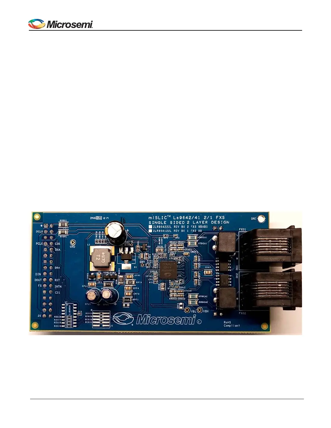
This arrangement for the two-channel line modules is as a single PBX network. The setup requires that the
ZLR964222L line module be installed on the SM2 receptacle on the ZTAP platform.
Figure 2 - ZLR964222L Line Module
The ZLR964222L line module is equipped with two FXS ports. Mini-PBX assigns extension numbers to each port,
which are typically 100 and 101 for the FXS ports.
• To make an FXS to FXS call, connect two telephone sets to the two FXS ports on the line module and go off-
hook on one of them.