EasyManua.ls Logo

MicroElektronika EasyPIC4 - Page 19

Default Icon
34 pages
Print Icon
To Next Page IconTo Next Page
To Previous Page IconTo Previous Page
Loading...
VCC
RA0
RA1
RA2
RA3
RA4
RA5
RA6
RA7
RB0
RB1
RB2
RB3
RB4
RB5
RB6
RB7
RC0
RC1
RC2
RC3
RC4
RC5
RC6
RC7
RD0
RE0
RD1
RE1
RD2
RE2
RD3
RE3
RD4
RD5
RD6
RD7
PORTA
PORTB
PORTC
PORTD
PORTE
VCC
PICxxxx
RA0
RA1
RA2
RA3
RC0
RC1
RA4
RA5
RE0
RE1
RE2
RC3
RD0
RD1
RC4
RD3
RD2
RC5
RC6
RC7
RD4
RD5
RD6
RD7
RB0
RB1
RB2
RB3
RB4
RB5
RB7
RB6
RC2
VDD
VSS
OSC1
OSC2
MCLR
VDD
VSS
0V while button
is pressed
+5V while button
is pressed
X1
8MHz
C6
22pF
C7
22pF
JP17
EasyPIC4 Users Manual
MIKROELEKTRONIKA SOFTWARE AND HARDWARE SOLUTIONS FOR THE EMBEDDED WORLD
1199
page
MikroElektronika
Development
tools
EasyPIC
ICD
4
PPUUSSHHBBUUTTTTOONN SSWWIITTCCHHEESS
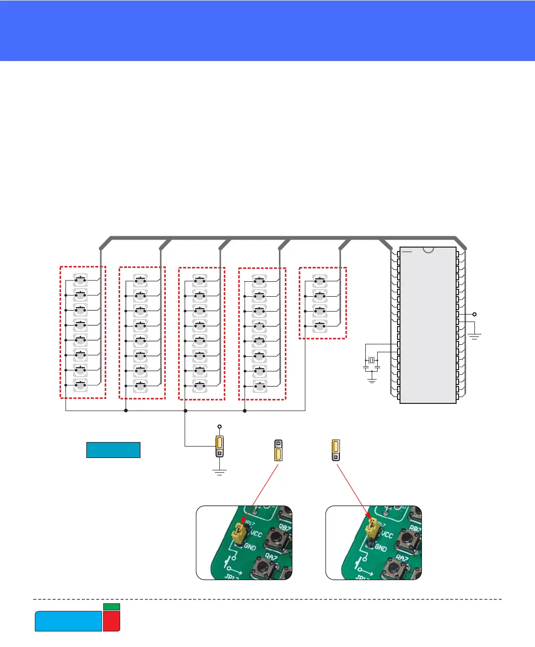
Figure 23.
Buttons schematics
Buttons connections to PORTA, PORTB, PORTC, PORTD and PORTE are shown
in Fig. 23. Jumper JP17 determines whether a button press will bring logical zero or
logical one to the appropriate pin.
When button is not pressed, pin state is determined by the pull-up or pull-down port
jumpers.
In the example shown in Fig. 23, JP17 is connected to +5V, therefore pressing the
buttons will bring logical one to the appropriate pins.