EasyManua.ls Logo

MicroElektronika EasyPIC4 - Page 20

Default Icon
34 pages
Print Icon
To Next Page IconTo Next Page
To Previous Page IconTo Previous Page
Loading...
EasyPIC4 Users Manual
2200
page
MIKROELEKTRONIKA SOFTWARE AND HARDWARE SOLUTIONS FOR THE EMBEDDED WORLD
MikroElektronika
Development
tools
PPUUSSHHBBUUTTTTOONN SSWWIITTCCHHEESS
EasyPIC
ICD
4
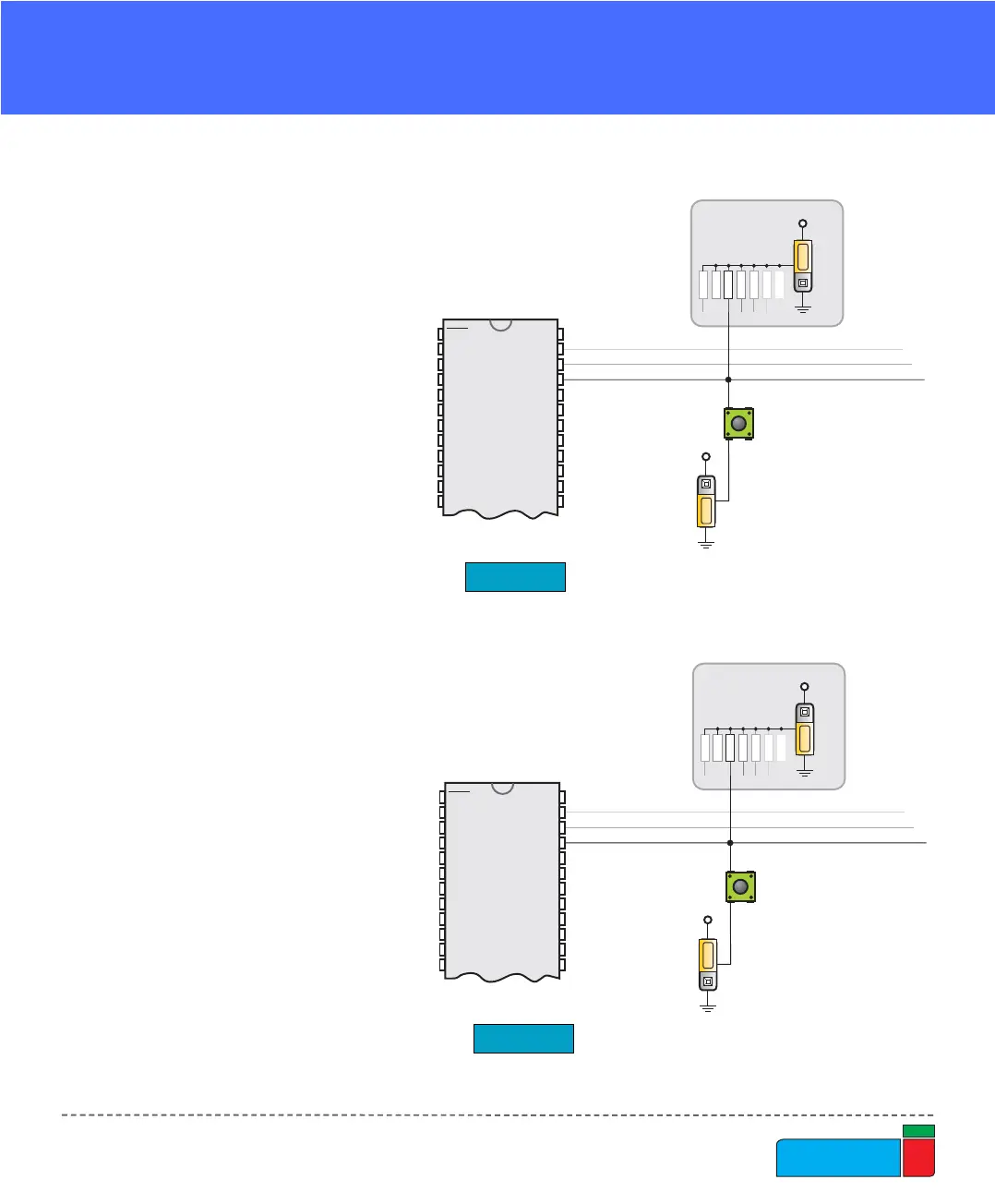
On Fig. 24 the JP21 switch is
set to pull-up, therefore when
the button is not pressed,
pull-up resistor pulls the
microcontrollers RB4 pin to
+5V.
A button press causes the
port pin to be connected to
ground (JP17 is in the lower
position).
Thus, only when the button is
pressed the microcontroller
will sense a logical zero; oth-
erwise the pin state will
always be logical one.
On Fig. 25 the JP21 switch is
set to pull-down, therefore
when the button is not
pressed, pull-down resistor
pulls the microcontrollers
RB4 pin to 0V.
A button press causes the
port pin to be connected to
+5V (JP17 is in the higher
position).
Thus, only when the button is
pressed the microcontroller
will sense a logical one; oth-
erwise the pin state will
always be logical zero.
RB4
PortB
pull-up
0V while pressed
vcc
DIP40
RA0
RA1
RA2
RA3
RA4
RA5
RE0
RE1
RE2
RD6
RD7
RB0
RB1
RB2
RB3
RB4
RB5
RB7
RB6
VDD
VSS
MCLR
VDD
VSS
vcc
JP21
JP17
RB4
PortB
pull-down
5V while pressed
vcc
DIP40
RA0
RA1
RA2
RA3
RA4
RA5
RE0
RE1
RE2
RD6
RD7
RB0
RB1
RB2
RB3
RB4
RB5
RB7
RB6
VDD
VSS
MCLR
VDD
VSS
vcc
JP21
JP17
Figure 24.
Figure 25.
Button with pull-up resistor
Button with pull-down resistor