B-2 APPENDIX B MDS 05-2415A01, Rev. A
bypass jumpers in place of U31 in the TTL configuration. The transmit data is fed into the
data processor U6.
Level shifting and wave shaping operations cause the data to resemble a smooth audio wave-
form. This waveform feeds into the modulation input of the transmitter. Deviation and center
frequency are controlled by the transmitter.
Unlike radios with analog modems installed, the transmitter does not transmit a constant
carrier at center frequency when RTS is raised and no data is being sent. It can transmit a
signal above or below the center frequency, depending upon whether the data is a mark or a
space.
With an RS-232 interface, a “Mark” (the normal resting state when no data is being sent),
causes the transmitted frequency to be 1.6 kHz below the nominal center. If the TXD line is
tied high (continuous Space), the frequency will be 1.6 kHz above the nominal center. While
continuous data is being sent, the frequency measures approximately the nominal channel
frequency as the carrier toggles back and forth about the center frequency.
For a TTL interface configuration, a “Mark” is a digital “high” or binary “1” and the “Space”
is a digital “low” or a binary “0”.
TC
RC
ETC
U7
RS-232
INTERFACE
TX
AUDIO OUT
RXD
TXD
PTT
TAE
DCD
5 V
REGULATOR
+ 10V
10 V
REGULATOR
+ 13V IN
RE
U7 U8
+ 5V
U3D
U3C U3B
SYNC-ASYNC
CONVERTOR
PROM
U5 U4
MODEM
RX AUDIO
S1
OPTION SELECT
SWITCHES
RUS
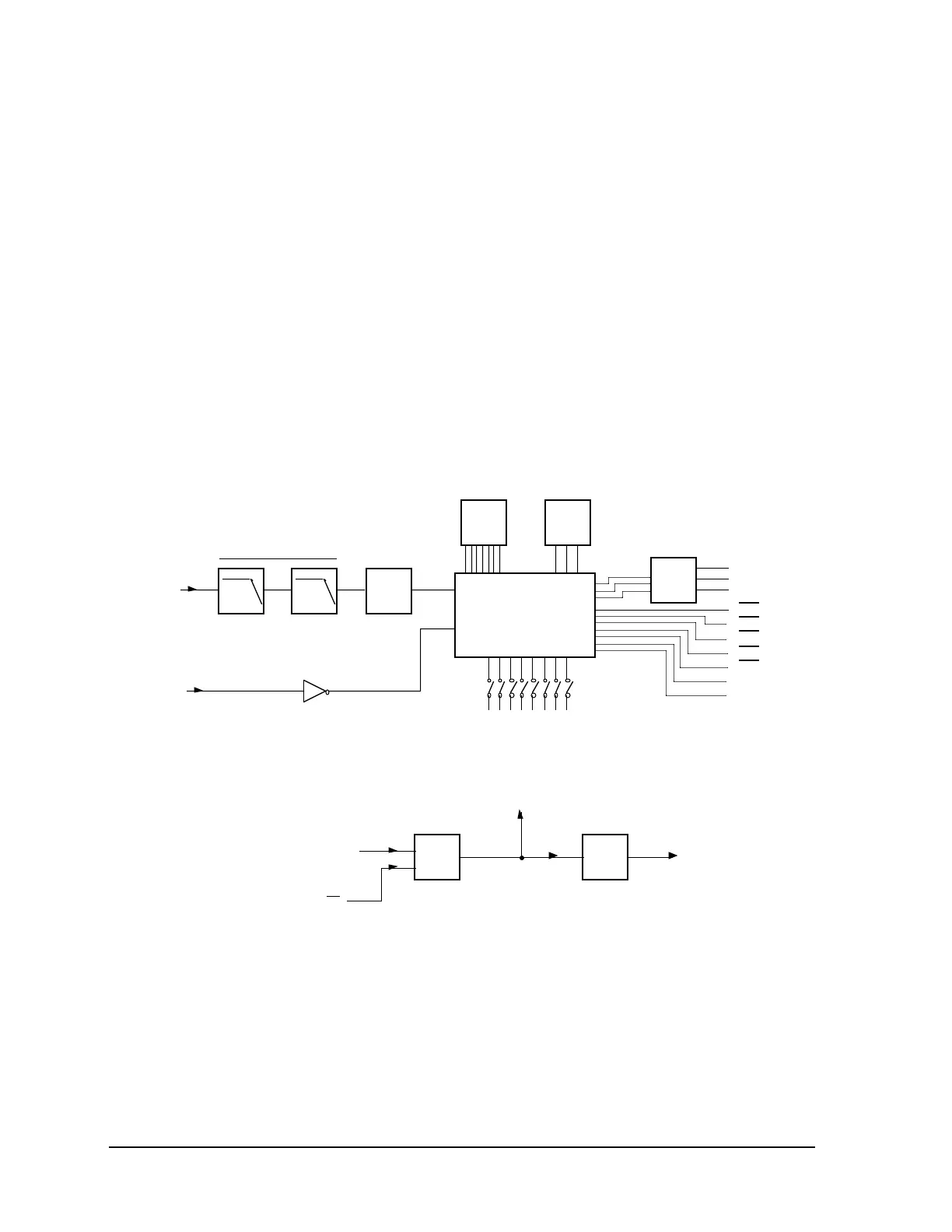
LOW PASS FILTER
U8
DATA
SLICER
DATA PROCESSOR
U6
POWER
REGULATORS &
CONTROL
Figure B-1. MDS 4800 bps Modem Block Diagram
Receive Data
While no carrier is detected, the squelch circuit in the receiver senses the lack of quieting and
forces the DCD low and RXD output to mark condition. It also biases the “slicer” circuit so
that it recognizes the very first mark-to-space transition correctly once a signal is received.