2-6 INSTALLATION MDS 05-2415A01, Rev. A
When using an internal modem, other pin functions of the DB-25 INTERFACE connector, such
as PTT, Receive Audio, Transmit Audio and RSSI are still active and should normally be left
open (unterminated). Connecting these pins to a computer terminal that also uses these pins
for auxiliary connections can cause improper operation.
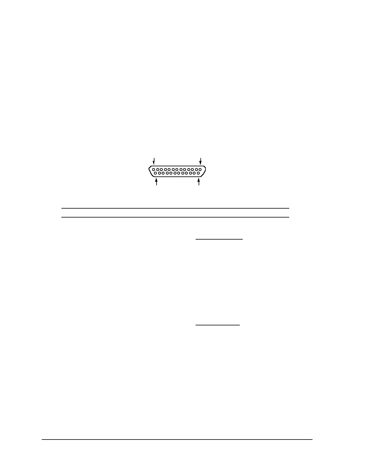
Pin connections for the transceiver’s
INTERFACE connector are summarized in Table 2-1 and
are described in greater detail later in this chapter.
NOTE
When using the TTL interface option, external 1 kΩ (1/8 W)
pull-up resistors are required between J1 Pins 2, 3, 4, 5 & 6 and
the logic source in the remote terminal unit (RTU).
Table 2-1. DB-25 Interface Connector Pin Functions
13 1
25 14
Viewed from Outside or from Plug’s Solder Cups
Pin Number and Function Pin Number and Function
1. Shield
2. Transmit Data In (TXD)*
3. Received Data Out (RXD)
4. Request-To-Send (RTS)*
5. Clear-To-Send (CTS)
6. Data Set Ready (DSR)
7. Signal Ground
8. Data Carrier Detect (DCD)
9. Transmit Audio Input*
10. Receiver Unsquelched Sense
11. Receiver Filtered Audio Output
12. Radio Disable*
13. Transmit Audio Output
14. Push-To-Talk (PTT)*
15. Transmit Clock (TC)
16. Push-To-Talk (PTT)
*
17. Receive Clock (RC)*
18. +13 Vdc
19. +8 Vdc
20.
No Connection
21. Received Signal Strength Indicator
(RSSI)
22. Loopback Test–Receive Audio Input*
(For local testing of loopback DTMF
decoder)
23. Open Diagnostics
24. External Transmit Clock (ETC)*
25. Out-of-Lock Alarm
* Input